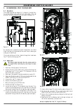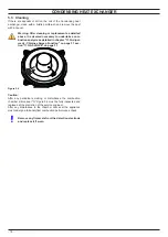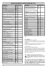
- 10 -
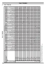
FAULT FINDING
4 FAULT FINDING
FAUL
T FINDING
Components to check
Section of the manual
(note ref. in brackets)
– (1)
– (2)
– (3)
21.1
– (4)
5
6
7.2
8.2
14.3
9.5
10
11.4
12.2
14.5
15.2
16
17
18.4
19.2
19.2
20.1
– (7)
–
–
–
Appliance lock–out (*)
Defect
Power supply line
Gas supply line
Flue pipes
Cond. drain pipe and trap
C.H. circuit
D.H.W. circuit
Condensing heat exchanger
D.H.W. heat exchanger
Pump
Diverter valve
D.H.W. flow
switch
Fuses (Electronic p.c.b.)
Main electronic p.c.b.
Boiler settings
Control panel electr. p.c.b.
Gas valve
Main circuit pressure switch
D.H.W. filter
Main circuit temp. probe
D.H.W. temp. probe
By–pass valve
Fan / air restrictor
Ignition / Detection electrode
Safety thermostat
Gas restrictor
Flue temp. probe NTC
Expansion vessel
Safety valve
Pressure gauge
External temp. probe
Display indicates ”E”
E01
+
A
B
D
C
E02
+
C
A
B
E03
+
A
E04
+
B
A
E05
+
A
E06
+
A
E07
+
A
E08
+
A
E10
+
A
B
E11
+
C
B
E12
+
A
E13
+
A
B
E14
+
A
C
B
E14
+
A
B
E18
+
B
A
E19
+
A
E20
+
A
B
E21
+
A
B
E22
+
B
A
The letter in the cells indicates the possible fault cause.
A
. . . . .
Z
indicates the most probably (
A
) to less probably (
. . . .
Z
)
Summary of Contents for 47-583-46
Page 2: ......
Page 50: ...50 SHORT SPARE PARTS LIST 6 2 3 4 7 8 10 9 11 12 18 19 20 21 13 14 15 16 17 1 5 Figure 21 1...
Page 51: ......

