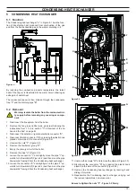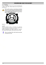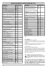
- 12 -
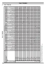
FAULT FINDING
FAUL
T FINDING
Components to check
Section of the manual
(note ref. in brackets)
– (1)
– (2)
– (3)
21.1
– (4)
5
6
7.2
8.2
14.3
9.5
10
11.4
12.2
14.5
15.2
16
17
18.4
19.2
19.2
20.1
– (7)
–
–
–
Appliance lock–out (*)
Defect
Power supply line
Gas supply line
Flue pipes
Cond. drain pipe and trap
C.H. circuit
D.H.W. circuit
Condensing heat exchanger
D.H.W. heat exchanger
Pump
Diverter valve
D.H.W. flow
switch
Fuses (Electronic p.c.b.)
Main electronic p.c.b.
Boiler settings
Control panel electr. p.c.b.
Gas valve
Main circuit pressure switch
D.H.W. filter
Main circuit temp. probe
D.H.W. temp. probe
By–pass valve
Fan / air restrictor
Ignition electrode / Detection
electrode
Safety thermostat
Gas restrictor
Flue temp. probe NTC
Expansion vessel
Safety valve
Pressure gauge
External temp. probe
No ”E” indication on display
The boile
r does not start either in C.H. or
D.H.W
. mode.
The control panel display OFF Fan still.
•
•
•
•
The
boile
r does not
supply D.H.W
. (cold wa
-
ter from the tap). Regular operation in C.H.
mode even during
a drawing of
f D.H.W
.
•
•
•
On C.H. mode the temperature of the main circuit reaches 90°C
and the
C.H.
system
does not heat. The boiler
operates correctly on D.H.W
.
mode.
•
•
•
Incorrect modulation.
•
•
•
•
Noisy bolier
.
•
•
•
•
•
•
Poor C.H. / D.H.W
. temperature (9).
•
•
•
•
•
Poor D.H.W
. temperature. Regular
opera
-
tion in C.H. mode.
•
•
•
(8)
•
Low
D.H.W
. flow
rate.
•
•
•
–
W
ater leaks from the safety valve during op
-
eration on C.H.
•
•
•
•
•
•
–
W
ater leaks from the safety valve
when the
boiler is of
f.
•
•
•
* Lock out is indicated as “
E
” on the display
.
Note
Useful information can be obtained also from the optical indication given by the appliance display (see section 4
.1)
.
1
Check for 230V~ between line (L) and neutral (N).
Verify the integrity of supply cable, plug and external fuses.
Check the polarity of line and neutral connection.
2
Check the gas supply pipe and isolation tap for gas tightness.
3
Check for soundness and absence of obstructions. V
erify
that
the
flue
terminal
is
correctly
installed
(see
clearances)
and ensure that exhaust gas is not sucked back by the boiler
.
4
Check
for
soundness
of
the
circuit
and
verify
its
correct
fillin
g
(see also installation manual).
5
A jammed by–pass could cause the over–heating of the main circuit and the intervention of the safety thermostat.
6
Using
the
flue
analyser
, check
the
CO
2
value
of
the
flue
gases.
This reading is a reference value for the gas valve setting.
7
Check the pressurization
of the expansion
vessel. Refer
to the installation manual for proper values.
8
D.H.W
.
pressure
too
high
or
flow
rate
too
high.
If
necessary
insert
a
flow
rate
limiter
(14.6).
9
The boiler do
esn’t reach the nominal heat input.
Summary of Contents for 47-583-46
Page 2: ......
Page 50: ...50 SHORT SPARE PARTS LIST 6 2 3 4 7 8 10 9 11 12 18 19 20 21 13 14 15 16 17 1 5 Figure 21 1...
Page 51: ......

