- 13 -
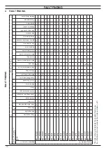
FAULT FINDING
4 .1 Display diagnostic
The display indications provide help in the diagnosis of fault find
-
ing.
The control panel display gives other information for the user.
The following table gives fault code, error and the reson for the
fault.
E01 +
Safety lockout due to failed ignition.
E02 +
Lockout due to safety thermostat.
E03 +
Generic lockout.
E04 +
Pump circulation failure, insufficient system
pressure or water pressure sensor not con-
nected.
E05 +
Control anomaly: fan.
E06 +
NTC heating delivery probe failure.
E07 +
D.H.W. NTC probe failure / Hot water tank
sensor failure.
E08 +
External NTC probe failure.
E10 +
Lockout due to tripping of the flue gas probe
and thermal fuse.
E11 +
Parasite flame.
E12 +
Return NTC probe failure.
E13 +
Delta T M-R > 40K.
E14 +
Temperature gradient circulation failure
(>2K/s).
E14 +
Pump fault or primary temperature above
105°C.
E18 +
No ΔT heating at startup.
E19 +
Auxiliary Input Probe Anomaly.
E20 +
EVG lockout (valve piloting hardware failure).
E21 +
EVG lockout (valve control Relay Failure).
E22 +
EVG lockout (flame after closing valve Ref.
EVG).
E23 +
Gas valve modulator disconnected.
E24 +
Anomaly due to probable chimney obstruc-
tion.
E25 +
Flame loss for more than 6 consecutive
times.
E26 +
Maximum deviation fault between the 2 heat-
ing NTC probes.
E40 +
Detection of incorrect mains frequency.
E42 +
Buttons fault.
E44 +
Fault of cumulative gas valve timeout without
flame.
E50 +
OT communication fault.
E62 +
Calibration request.
E65 +
System fails to control combustion and exits
modulator control parameters.
E68 +
Probably low gas pressure.
E77 +
System out modulator control parameters.
E79 +
System out modulator control parameters.
E78 +
Possible low gas pressure.
E89 +
Internal error (usually hardware) or problems
with the mains electrical supply (excessive
distortion of waveform).
E91 +
Maximum number of lockouts reached.
E97 +
Power supply voltage low.
E99 +
Card not configured.
L01
Primary limitation in D.H.W. mode.
Maintenance required.
The wrench symbol is flashing (without show
-
ing any error).
4 .2 Programming the maintenance period
1 To enter in the parameters setting mode press at the same
time the 2 keys "A" and "C" (Figure 4.1) and hold in for 5 sec-
ond until the display shows Figure 4.2.
Figure 4 .1
A
B
C
Figure 4 .2
2 Scroll the various menus using keys "A" or "C" (Figure 4.1)
until the LCD display indicates the letters
PAr
(Figure 4.3).
3 To enter the selected menu press key "B" (Figure 4.1) for 1
second.
Figure 4 .3
4 Scroll the various menus using keys "A" or "C" (Figure 4.1)
until the LCD display indicates the letters
P34
until the LCD
display indicates the value of parameter 34 (e.g.
12
default
value) Figure 4.4.
Figure 4 .4
5 To enter the selected parameter press key "B" (Figure 4.1)
for 1 second. The display will show the following (Figure 4.5).
Summary of Contents for 47-583-46
Page 2: ......
Page 50: ...50 SHORT SPARE PARTS LIST 6 2 3 4 7 8 10 9 11 12 18 19 20 21 13 14 15 16 17 1 5 Figure 21 1...
Page 51: ......

