- 46 -
FLUE TEMPERATURE PROBE NTC AND SAFETY THERMAL FUSE
19 FLUE TEMPERATURE PROBE NTC AND
SAFETY THERMAL FUSE
19 .1 Function
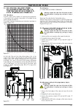
The Flue temperature probe NTC and Safety thermal fuse "A"
in Figure 19.1 and Figure 19.2 senses the temperature of the
combustion products that flow through the condensing heat ex
-
changer.
Figure 19 .1
A
If the temperature of the combustion products circuit reaches the
limit temperature, the Flue temperature probe NTC reduces the
gas flow rate to the burner. The temperature of the combustion
products should decrease to a safe value temperature.
In the case that the temperature of the combustion products
reaches a potentially dangerous value, the Safety thermal fuse
stops the boiler operation (lock-out).
This allows the use of plastic materials for the flue outlet pipes
and bends.
The use of kits different from the original isn’t however allowed,
since the flue pipes are integral parts of the boiler.
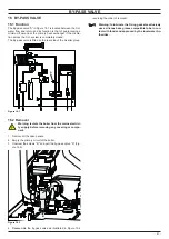
Figure 19 .2
A
B
A Flue temperature probe NTC and Safety thermal fuse "A" in
Figure 19.1 and Figure 19.2 is also connected in series with the
Flue temperature probe NTC and acts as a safety device in ex-
treme case of incorrect operation of the Flue temperature control
system.
Reaching the breakdown temperature it opens the circuit and
locks out the boiler.
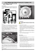
In case of intervention of this safety device the heat exchanger
(part shown in Figure 19.3) may be damaged and must be re-
placed.
Figure 19 .3
19 .2 Removal
Warning: isolate the boiler from the mains electrici-
ty supply before removing any covering or compo-
nent .
1 Remove all the case panels.
2 Disconnect the connector "B" from the Flue temperature
probe NTC and Safety thermal fuse by pressing the plastic
hook placed on the side of the connector (Figure 19.2).
3 Unscrew and remove the Flue temperature probe NTC and
Safety thermal fuse "A" (Figure 19.2) from the condensing
heat exchanger.
4 Assemble the Flue temperature probe NTC and Safety ther-
mal fuse carrying out the removal operations in reverse se-
quence.
5 Ensure the probe seal is in a good serviceable condition to
avoid POC and condensate leakage.
19 .3 Checks
Overheat temperature value
1 Set the temperature control knobs to their max. position and
run the boiler in D.H.W. and C.H.
2 Allow the boiler to reach its maximum operating temperature
(monitor the temperature gauge on the instrument panel).
The boiler should maintain a temperature below that of the
Flue temperature probe NTC and Safety thermal fuse and no
overheat intervention should occur.
Temperature-resistance relationship.
1 Remove the Flue temperature probe NTC and Safety thermal
fuse (see section "19.2 Removal" on page 46).
2 Measure the Flue temperature probe NTC and Safety ther-
mal fuse electrical resistance at the ambient temperature and
check it according to the graph in (Figure 19.4).
Summary of Contents for 47-583-46
Page 2: ......
Page 50: ...50 SHORT SPARE PARTS LIST 6 2 3 4 7 8 10 9 11 12 18 19 20 21 13 14 15 16 17 1 5 Figure 21 1...
Page 51: ......


