- 48 -
CONDENSATE TRAP
20 CONDENSATE TRAP
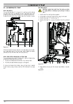
20 .1 Function
The condensate trap "A" in Figure 20.1 and Figure 20.2 allows
the discharge of the condensate via the condensate drain pipe
avoiding in the mean time the escape of combustion products.
A plastic ball closes the trap outlet in case that the trap is empty.
Figure 20 .1
A
If the drain pipe becomes blocked, or condensate cannot drain,
the condensate level in the trap rises until it affects the flame
detection probe, this will cause the boiler lock-out.
20 .2 Check the cleanness of the trap
The condensate drain pipe "A" (Figure 20.2) does not require any
particular maintenance but just check:
1 That no solid deposits have formed, if so remove them.
2 That the condensate drain piping is not clogged.
To clean the inside of the siphon, remove it and turn it upside
down to remove any dirt (see section "20.3 Removal" on page
48).
20 .3 Removal
Warning: isolate the boiler from the mains electrici-
ty supply before removing any covering or compo-
nent .
1 Remove the front and right case panels.
2 Using pliers, remove the spring "B" moving it to the left.
3 Remove the pipe "C" from the trap "A".
4 Remove the trap "A", moving it upwards; from the grommet
"D".
Figure 20 .2
A
A
B
C
D
5 Reassemble carrying out the removal operations in reverse
order.
Figure 20 .3
Summary of Contents for 47-583-46
Page 2: ......
Page 50: ...50 SHORT SPARE PARTS LIST 6 2 3 4 7 8 10 9 11 12 18 19 20 21 13 14 15 16 17 1 5 Figure 21 1...
Page 51: ......

