- 58 -
INST
ALLA
TION
COMMISSIONING
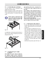
Fig. 7.6
A
B
23
If it does not comply with the required pres-
sure check the gas supply line and governor
for faults and/or correct adjustment.
Where the boiler is connected to a gas
supply which has a zero set governor
then it is necessary under the Gas Safe
(Installation and Use) Regulations 26.9.
to perform a combustion analysis test
for CO/CO
2
(The limits for the boiler is
given in
section "Technical data Activ
A 12OV" to page 24 , section "Technical
data Activ A 15OV" to page 26 , section
"Technical data Activ A 20OV" to page
28 and section "Technical data Activ A
25OV" to page 30 : CO
2
contents / other
fl ue gas fi gures) and complete the Certif-
icate of Exemption section of the Bench-
mark.
Important: after the checks all of the test
points must be sealed.
7.8
Lighting the boiler
Some products incorporate an anti cycling
time delay. It is normal when fi rst switch-
ing the boiler on for the boiler to operate
on heating for a few seconds then switch
off. After 3-4 minutes has elapsed the boiler
will then re ignite and operate perfectly nor-
mally.
If external controls are fi tted (e.g. Time clock,
room thermostat) ensure they ”call for heat”.
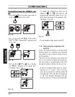
• Electrically power the boiler by switching on
the double pole isolation switch. The LCD
will display, the
symbol ( Fig. 7.7 ).
Fig. 7.7
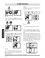
• Press the 9 key for 2 seconds until
symbol appears on the display Fig. 7.8 .
Fig. 7.8
9
10
11
12
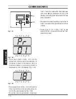
The LCD display displays the boiler temper-
ature (primary circuit) and the
sym-
bol; the
symbol slowly fl ashes Fig. 7.9 .
Fig. 7.9
°C
• Open the gas cock
• Make sure that the ambient thermostat is
in the “heat request” position”.
Summary of Contents for Activ A 120V
Page 20: ...20 USE USEFUL ADVICE Fig 3 7 14...
Page 81: ...81 NOTES...
Page 82: ...82 NOTES...
Page 83: ......


