background image

- 73 -

MAINTENANCE

MAINTENANCE

9  

MAINTENANCE

9.1 Warnings

The procedures detailed in this chapter 

must be carried out only Gas Safety Reg-
istered Engineer

. Thus you are advised to 

contact an Authorised Service Agent. 

For Ireland (IE), the servicing work must 
be carried out by a competent Person. 

For effi cient and continuous operation of the 
boiler you are advised to have, at least once 
a year, maintenance and cleaning done by 
an Approved Service Engineer. 

Isolate the appliance from the electricity 
supply

 by turning off the fused spur isola-

tion switch adjacent to the appliance and 
turn off the gas cock, before carrying out 
any procedures, whatsoever, for cleaning, 
maintenance, opening or dismantling boiler 
panels. The Engineer should complete the 
Service Interval Record at the back of the 
manual.

9.2  

Dismantling the external 
panels

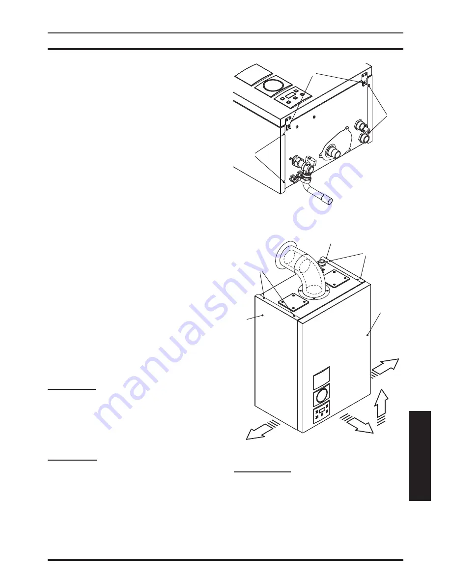
Front panel

• Unscrew screws  A and remove the front 

panel  

D by pulling it and pushing it to-

wards the top so that it is freed from the 
top housings ( Fig. 9.1  and  Fig. 9.2 ).

Side panels

Loosen screws " 


B

 -


F


"


and "  C 

-


H


"


in  Fig. 9.1  

and remove the two side panels  E and  G by 
pulling towards the outside.

Fig. 9.1


Fig. 9.2


Control panel

Turn the controls panel  I , as shown in fi gure 
 Fig. 9.3 , to access in an optimal manner the 
components inside the boiler.

Summary of Contents for Activ A 120V

Page 1: ...g fanflue roomsealed high efficiency gas boiler User manual and Installation instructions ActivA Models G C Appl No Activ A 12OV 41 583 14 Activ A 15OV 41 583 15 Activ A 20OV 41 583 16 Activ A 25OV 41...

Page 2: ...eat that otherwise would be lost DANGER The indications marked with this symbol must be observed to pre vent accidents of mechanical or generic origin e g injuries or bruises DANGER The indications ma...

Page 3: ...u are advised to have a Gas Safety Registered Engineer check that the installation of the gas supply is gas tight is of the correct gauge for the flow to the boiler is fitted with all the safety and c...

Page 4: ...en or by those unfamiliar with its operation must not be exposed to weather conditions During the operation it is quite normal that the boiler produces a white plume of conden sation vapour from the f...

Page 5: ...and throat Vapour is harmful Inflammable do not extinguish with water Precautions Do not incinerate Avoid contact with broken leaking phials Do not purposely puncture First aid medical attention must...

Page 6: ...rnal controls such as a room thermostat By following this procedure if you have a subse quent problem following the addition of an external control you can eliminate the boiler from your fault analysi...

Page 7: ...ps 57 7 6 Checking the gas supply pressure 57 7 7 Checking the inlet pressure 57 7 8 Lighting the boiler 58 7 9 Enabling functioning of the external temperature probe by the remote control 59 7 10 Set...

Page 8: ...printed on bottom right side Fig 1 1 1 2 6 4 1 Controls panel 2 House for possible time switch c h control 1 2 Isolation valves Fig 1 2 3 5 6 7 4 8 3 Gas supply label 4 C h flow pipe 5 Gas inlet valve...

Page 9: ...Reset Stand by Winter key 10 C h temperature reduce key 11 C h temperature increase key 12 LCD display RESET that takes all parameters back to the factory value occurs only by setting parameter 08 04...

Page 10: ...eral lockout Er 10 Flue probe intervention lockout Er 14 Faulty pump or primary temperature above 105 C LCD FUNCTION Er 15 None or too low water flow Faulty pump temp difference between probes higher...

Page 11: ...m perature flashing Delayed burner ignition for setting the system uu flashing tempera ture flashing LCD FUNCTION Boiler in chimney sweep functioning mode The chimney sweep is activated by setting par...

Page 12: ...h w supply checking that the pressure in dicated on pressure gauge is not lower than that shown in Fig 2 2 If the pressure reading on the pressure gauge is below that shown in Fig 2 2 then the system...

Page 13: ...required pressure 2 3 Ignition Check that the gas supply cock located in the lower part of the boiler and the valves are open Fig 2 3 Fig 2 3 Open position Turn on the electricity supply to the boil e...

Page 14: ...on the LCD display by means of the missing symbol Power request in c h power When the boiler has a power request in the c h mode the symbol is displayed on the display followed by an increase of the c...

Page 15: ...he electricity supply to the boil er by means of the fused spur isolation switch Shut off the gas supply cock fitted under the boiler and the valves for the water cir cuits Fig 2 11 Fig 2 11 Close pos...

Page 16: ...2 Therefore when the boiler is not lit and used in cold weather with consequent risk of freezing do not switch off the boiler at the fused spur isolation switch or close the gas inlet cock If the boi...

Page 17: ...the writing reset see LCD general features to page 10 appear on the LCD display it indi cates that the safety lock out has stopped the boiler The display background flashes Fig 3 3 Fig 3 3 RESET RESET...

Page 18: ...heating circuit is not close to 3 bars In this case temperature rise in the circuit can cause the pressure relief valve to open So that this does not happen and to decrease the pressure to a normal v...

Page 19: ...or absence ol flow 04E Faulty fan control system 05E Faulty c h temp probe NTC 06E Faulty external temp probe NTC 08E Faulty flue temp probe NTC 09E Flue probe intervention lockout 10E Flame detection...

Page 20: ...20 USE USEFUL ADVICE Fig 3 7 14...

Page 21: ...21 INSTALLATION TECHNICAL INFORMATION 4 TECHNICAL INFORMATION 4 1 Overview Fig 4 1 14 19 20 26 27 23 22 29 21 7 13 25 24 16 28 17 18 15 30 31 4 6...

Page 22: ...C h flow pipe 5 Gas inlet valve 6 C h return pipe 7 Condensate drain pipe 30 31 32 17 29 26 22 5 6 6 8 7 4 4 25 23 20 15 16 28 33 14 19 Fig 4 2 13 Main circuit drain valve 14 Flue temperature probe NT...

Page 23: ...ve 23 Gas valve inlet test point 24 Control box containing External tem perature probe terminal block remote terminal block d h w tank terminal block power supply terminal block external controls pump...

Page 24: ...ressure loss in 1000 l h Pa 12000 mbar 120 Seasonal effiency G20 c band A 90 1 Seasonal effiency G31 c band A 91 1 to the minimum useful output A referred to the net calorific value at 15 C and 1013 2...

Page 25: ...Nominal heat flow rate A E kW 12 Exhaust temperature E C 62 Mass flow rate E kg s 0 0053 Flue gas figures Nominal heat input A E kW 12 0 CO2 content with gas G20 8 9 9 8 O2 content with gas G20 3 9 C...

Page 26: ...ressure loss in 1000 l h Pa 12000 mbar 120 Seasonal effiency G20 c band A 90 0 Seasonal effiency G31 c band A 91 1 to the minimum useful output A referred to the net calorific value at 15 C and 1013 2...

Page 27: ...Nominal heat flow rate A E kW 15 Exhaust temperature E C 62 Mass flow rate E kg s 0 0064 Flue gas figures Nominal heat input A E kW 15 0 CO2 content with gas G20 8 9 9 8 O2 content with gas G20 3 9 C...

Page 28: ...ressure loss in 1000 l h Pa 12000 mbar 120 Seasonal effiency G20 c band A 90 3 Seasonal effiency G31 c band A 91 3 to the minimum useful output A referred to the net calorific value at 15 C and 1013 2...

Page 29: ...Nominal heat flow rate A E kW 20 Exhaust temperature E C 68 Mass flow rate E kg s 0 0088 Flue gas figures Nominal heat input A E kW 20 0 CO2 content with gas G20 8 9 9 8 O2 content with gas G20 3 8 C...

Page 30: ...ressure loss in 1000 l h Pa 11000 mbar 110 Seasonal effiency G20 c band A 90 3 Seasonal effiency G31 c band A 91 3 to the minimum useful output A referred to the net calorific value at 15 C and 1013 2...

Page 31: ...heat flow rate A E kW 25 Exhaust temperature E C 75 Mass flow rate E kg s 0 0111 Flue gas figures Nominal heat input A E kW 25 0 CO2 content with gas G20 8 9 9 8 O2 content with gas G20 3 8 CO content...

Page 32: ...rent edi tion of I S 813 2002 Domestic Gas Installa tions the current Building Regulations and reference should be made to the current ETCI rules for electrical installations 5 2 Location of appliance...

Page 33: ...ners 450 H From external corners 300 I Above ground or balcony lev el 300 J From a next door boundary 2500 K From a terminal facing a termi nal 2500 L From an opening in the car port e g door window i...

Page 34: ...al regulations in force The condensate pipe must be fitted in ac cordance with Building Regulations Drain pipe material should be resistant to acid as the condensate is slightly acid with a pH less th...

Page 35: ...attention should be paid to pipes passing through ventilated spaces in roofs and under floors Central heating system The appliances are designed for open vented central heating water systems but may b...

Page 36: ...he boiler High resistance microbore systems may re quire a higher duty pump Flow rate If it is necessary to alter the flow rate the system can be fitted with a lockable balanc ing valve in the main fl...

Page 37: ...S5449 and BS7074 Part 1 Example For an initial design pressure of 0 7 bar the minimum total vessel volume required is 0 063 x Total System Volume A higher initial design pressure requires a larger vol...

Page 38: ...ovision should be made for replacing wa ter loss from the system using a make up bottle mounted in a position higher than the top point of the system connected through a non return valve to the return...

Page 39: ...tant the debris from the existing system is fully removed in order to ensure the efficiency of the new appliance is maintained Details on flushing procedure are given in the section Initial filling of...

Page 40: ...a tions and any local regulations which apply Reference should be made to the current ETCI rules for electrical installations For Ireland IE refer to I S 813 2002 The boiler is supplied for connection...

Page 41: ...ments of the distribu tors and comply with current Regulations and laws in force The safety relief valve and the condensate drain must be connected to a suitable drain or discharge in a safe manner Th...

Page 42: ...product in the circulating water The latter option in particular not only cleans out the system but also has an anti corrosive effect by promoting formation of a protective skin on metal surfaces and...

Page 43: ...Gas c h return c h flow 22 Condensate drain 25 plastic sizes in mm o d Condensate drain to be realised with min pipe 30 mm 6 6 Central heating service con nections Mount the bracket of the prepiping k...

Page 44: ...pipe open system or fitting to an automatic air vent sealed sys tem The remaining pipe must be solder sealed UPWARDS FLOW Fig 6 3 J K L Fig 6 4 J K L DOWNWARDS FLOW Fig 6 5 J L K Fig 6 6 J L K Mount t...

Page 45: ...1 5 degrees 25 mm per me ter The terminal must be higher than the infeed boiler side The single coaxial pipe with terminal must be horizontal because the drain pipe is al ready angled The following ki...

Page 46: ...r is supplied within the twin pipe kit box Fig 6 9 Air intake adapter Restrictor Gasket N B The air intake and the flue outlet must not terminate on opposite sides of the building EN 483 Fig 6 10 Type...

Page 47: ...his kit allows the combustion air to be sucked up and expel the burnt gases di rectly to the outside through a telescopic co axial flue 450 950 mm Fig 6 13 90 1 m 45 0 5 m 90 0 85 m 45 0 65 m 60 mm 60...

Page 48: ...ve brown wire and the neutral blue wire External 3A fuse or fused plug with same current rating is recommended Do not connect live wires to terminals to which the room thermostat must be connected Con...

Page 49: ...follow the route indicated in Fig 6 17 Fig 6 17 Allow the cables to exit the boiler by using the relevant cable clamps Q Fig 6 18 Fig 6 18 Q 6 10 Electric connection of pump Use the clamps indicated i...

Page 50: ...acts of the Ambient Thermostat Fig 6 21 N L 3 2 1 Room thermostat 230V rating T Fig 6 22 Room thermostat 1 2 3 L N with delay resistor 230V rating T The thermostat must be insulation class II or must...

Page 51: ...24 and Fig 6 25 are divided in two parts The upper shows the single compo nents used on the diagrams with their con nection to the 10 way junction box The bold numbers represent the terminal of the ju...

Page 52: ...m thermostat A B 5 4 Cylinder thermostat C 1 2 8 7 6 GY WH OR GRYE BU 2 3 8 5 7 MAINS 230V a c Switched 3 Amp fused spur L N 2 3 1 Programmer HTG HW OFF HW ON L N 2 1 4 6 7 10 way junction box Valve c...

Page 53: ...r HTG HW OFF HW ON L N Do not remove room thermostat link Room thermostat A B 4 5 Cylinder thermostat C 1 2 8 7 6 GY WH OR GRYE BU 2 3 8 5 7 MAINS 230V a c Switched 3 Amp fused spur L N 2 3 1 Programm...

Page 54: ...cated in Fig 6 17 Allow the cables to exit the boiler by using the relevant cable clamps Q Fig 6 18 6 13 Installation of the external temperature probe optional The external probe must be installed on...

Page 55: ...shall be carried out by a competent person i e polarity earth con tinuity resistance to earth and short circuit If a fault has occurred on the appliance the fault finding procedure should be followed...

Page 56: ...apillary Pressure gauge NOTE THESE COMPONENTS ARE NOT SUPPLIED BY BIASI UK LTD Do not use the pressure relief valve to drain the system be cause dirt or debris could pre vent the valve seating correct...

Page 57: ...lue and a gas supply pressure of 20 mbar Any variation in gas supply pressure or flue length may result in the customer experiencing a harmonic noise from the boiler In these circumstances it may be n...

Page 58: ...f the Bench mark Important after the checks all of the test points must be sealed 7 8 Lighting the boiler Some products incorporate an anti cycling time delay It is normal when first switch ing the bo...

Page 59: ...RESET Press the reset key on the boiler control panel 9 Fig 7 8 to reset its functioning For the first lighting up and following main tenance procedures for the gas supply it may be necessary to repea...

Page 60: ...ning without the probe connected If the boiler is NOT EQUIPPED with the re mote control optional refer to Fig 7 15 Fig 7 15 External temperature C 20 20 15 10 5 0 5 10 15 20 25 30 40 50 60 70 80 C h f...

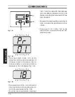
Page 61: ...g 7 17 9 10 11 12 Fig 7 18 Scroll the various parameters using keys 10or 11until the letters Pr that alternate with code 15 are displayed on the LCD display indicating that parameter 15 Fig 7 19 has b...

Page 62: ...he remote control connected Act on the programming of the REMOTE control to select the setting of the K coef ficient Electrically feed the boiler by activating the bipolar switch envisioned during in...

Page 63: ...vated Fig 7 26 Press keys 9and 11 Fig 7 24 at the same time until the value of parameter 11 10 60 seconds Fig 7 27 is displayed on the LCD display Fig 7 27 It is possible to modify parameter 11 by 00...

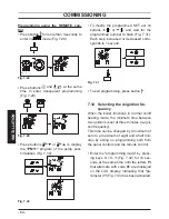
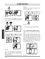
Page 64: ...r decreased corre sponds to 1 second Fig 7 31 To exit programming press button 7 12 Selecting the reignition fre quency When the boiler functions in normal on off heating mode the minimum time between...

Page 65: ...s to99 600s using keys 10or 11 each increase or reduction by a unit on the display corresponds to 6 seconds By pressing key 9 Fig 7 32 confirmation of the inserted value is obtained Press keys 9and 10...

Page 66: ...alf minutes Each step increased or decreased corre sponds to 2 seconds To modify the programmed SET act on buttons or and wait for the number programmed to flash Fig 7 39 Fig 7 39 To exit programming...

Page 67: ...olator Explain the proper use and adjustment of all system controls this will ensure the great est possible fuel economy Explain the function and use of the function selector Explain and demonstrate t...

Page 68: ...are displayed on the LCD display indicating that pa rameter 01 Fig 7 43 has been activated Fig 7 42 9 10 11 Fig 7 43 Scroll the various parameters using keys 10or 11until the letters Pr that alternate...

Page 69: ...rol p c b PARAMETER DIGIT VALUES Boiler type to be updated with the complete range Pr 01 Not used Pr 02 Not used Pr 03 Not used Pr 04 Gas type Pr 05 Not used Pr 06 PARAMETER DIGIT VALUES C h flow max...

Page 70: ...and 10 Fig 7 47 at the same time to exit without changing the value re turn to the parameters list Fig 7 48 Scroll the various parameters using keys 10or 11until the letters Pr that alternate with cod...

Page 71: ...correctly re placing the gas restrictor Fig 8 2 referring to the section Technical data Activ A 12OV to page 24 section Technical data Activ A 15OV to page 26 section Technical data Activ A 20OV to p...

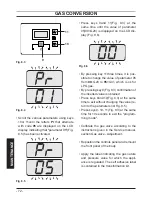
Page 72: ...m 00 G20 to 05 G31 which is ok for LPG gas By pressing key 9 Fig 8 3 confirmation of the inserted value is obtained Press keys 9and 10 Fig 8 3 at the same time to exit without changing the value re tu...

Page 73: ...tion switch adjacent to the appliance and turn off the gas cock before carrying out any procedures whatsoever for cleaning maintenance opening or dismantling boiler panels The Engineer should complete...

Page 74: ...of the boiler and simultaneously push the front case panel Duntil it is completely hold in place Fig 9 4 step 1 2 Repeat the same operation on the op posite side of the front panel D Fig 9 4 step 3 4...

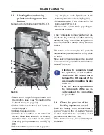
Page 75: ...e outside If the condensate primary exchanger ele ments are dirty notable only after removing the burner body brush them using a bristle brush and remove the dirt using a suction device The burner doe...

Page 76: ...Gas valve Ad justment of the Service manual Fig 9 7 Flue analysis points 9 9 Checking the condensate drain pipe The condensate drain pipe 25 Fig 9 8 does not require any particular mainte nance but j...

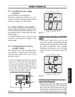
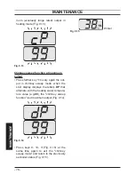
Page 77: ...making check and control operations easier Enter in programming mode by pressing keys 9 10 11 Fig 9 10 for 10 seconds at the same time until the letters Pr that al ternate with code 01 are displayed o...

Page 78: ...in the out put in chimney sweep mode when the LCD display displays the letters DP that alternate with the heating water tempera ture value e g 99 the chimney sweep function is at maximum output Fig 9...

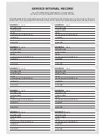
Page 79: ...MANUFACTURER S INSTRUCTIONS THE SYSTEM CLEANER USED THE INHIBITOR USED GAS RATE BURNER OPERATING PRESSURE IF APPLICABLE CENTRAL HEATING FLOW TEMPERATURE CENTRAL HEATING RETURN TEMPERATURE m3 hr ft hr...

Page 80: ...DATE SERVICE 3 ENGINEER NAME COMPANY NAME TEL No Gas Safe Register ID CARD SERIAL No COMMENTS SIGNATURE DATE SERVICE 4 ENGINEER NAME COMPANY NAME TEL No Gas SafeRegister ID CARD SERIALNo COMMENTS SIGN...

Page 81: ...81 NOTES...

Page 82: ...82 NOTES...

Page 83: ......

Page 84: ...Biasi UK Ltd Commercial Road Leamore Enterprise Park WALSALL WS2 7NQ Tel 01922 714 600 www biasi co uk 1796220180 17962 2018 0 4810 84A5 UK 01 12 2010 N...

Reviews: