- 42 -
INST
ALLA
TION
INSTALLATION
are approved and in the case of flue pipes, it
is necessary to use materials compatible with
condensation products.
During the pipes dimensioning phase, take
into consideration the static pressure residue
of the fan:
Useful static pres
-
sure at nominal heat
input
16 kW
90
Pa
25 kW
90
Pa
35 kW
90
Pa
Overheated flue
16 kW
90
°C
25 kW
93
°C
35 kW
98
°C
Maximum recircula
-
tion of CO
2
in the
suction duct
16 kW
0,97
%
25 kW
0,95
%
35 kW
0,95
%
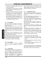
Roof flue exhaust kit (
Fig. 6.11)
Coaxial pipe Ø 80/125 mm with a nominal
height of 0.96 m.
This kit exhausts directly to the roof.
Fig. 6.11
45°
90°
Ø 125
Type C
33
Extensions are available for reaching the
maximum height.
Its maximum height with extension is 10.
Bends of Ø 80 mm at 90° and at 45° are avail
-
able that reduce the maximum total length of
the pipes by:
For the bend of 45° loss
0,5 m
For the bend of 90° loss
1 m
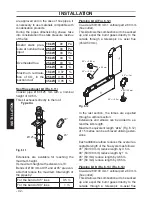
Pluming kit A (Fig. 6.12)
Co-axial ø 60/100 mm + vertical part ø 60 mm
(flue outlet).
This kit allows the combustion air to be sucked
up and expel the burnt gases directly to the
outside through a telescopic co- axial flue
(450-950 mm).
Fig. 6.12
90°=---1 m
45°=---0,5 m
90°=---0,85 m
45°=---0,65 m
ø 60 mm
ø 60/100 mm
In the last section, the fumes are expelled
through a vertical section.
Extensions and elbows can be added to ex
-
tend the kit’s length.
Maximum equivalent length “
a+b
” (Fig. 6.12)
of 15 metres can be achieved utilising exten
-
sions.
Each additional elbow reduces the overall ac
-
ceptable length of the flue system as follows:
45° (60/100 mm) reduce length by 0,5 m.
90° (60/100 mm) reduce length by 1 m.
45° (60 mm) reduce length by 0,65 m.
90° (60 mm) reduce length by 0,85 m.
Pluming kit B (Fig. 6.13) (Fig. 6.14)
Co-axial ø 60/100 mm + vertical part ø 60 mm
(flue outlet).
This kit allows the combustion air to be sucked
up and expel the burnt gases directly to the
outside through a telescopic co-axial flue


