- 44 -
INST
ALLA
TION
INSTALLATION
•
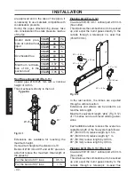
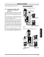
Identify the terminal block cover lid "R" (Fig.
6.16) and open it.
Fig. 6.16
R
Electric power supply connection
•
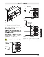
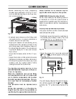
Connect the electric power supply cable
coming from the fused spur isolation switch
to the power supply terminal block of the
boiler Fig. 6.17 keeping the same connec
-
tions for the live (brown wire) and the neutral
(blue wire). External 3A fuse or fused plug
with same current rating is recommended.
• Do not connect live wires to terminals to
which the room thermostat must be con-
nected.
• Connect the earth cable (yellow/green) to
an effective earth plant.
The earth cable must be the long-
est of the electric power supply
cables.
The appliance's electric power supply cable or
wire must have a section no less than 0.75
mm
2
, it must be kept away from hot or sharp
parts and however conform to the technical
regulations in force.
Fig. 6.17
Ambient
thermostat
External
Probe
Electric
power supply
Remote
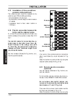
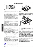
The route of the boiler and ambient thermo
-
stat's electric power supply cable or wires
must follow the route indicated in Fig. 6.18
.
Fig. 6.18
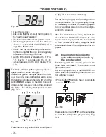
Allow the cables to exit the boiler by using the
relevant cable clamps S (Fig. 6.19).


