background image

Wall hung, fanflue, roomsealed, high efficiency gas boiler

User manual and

Installation instructions

Advance Plus

Models 

G.C. Appl. No.

Advance Plus 16S 

41-583-22

Advance Plus 25S 

41-583-23

Advance Plus 30S 

41-583-24

Summary of Contents for Advance Plus 16S

Page 1: ...hung fanflue roomsealed high efficiency gas boiler User manual and Installation instructions Advance Plus Models G C Appl No Advance Plus 16S 41 583 22 Advance Plus 25S 41 583 23 Advance Plus 30S 41 5...

Page 2: ...ter systems in the UK and to encourage regular servicing to optimise safety efficiency and performance Benchmark is managed and promoted by the Heating and Hot water Industry Council For more informat...

Page 3: ...a means of complying with the appropriate Building Regulations England and Wales All installations must be notified to Local Area Building Control either directly or through a Competent Persons Schem...

Page 4: ...ater to a temperature less than boiling point must be connected to a central heating system and or a hot water supply system com patible with its performance and output can be used only for those purp...

Page 5: ...skin Thermostat Temperature gauge Description Sealed phial and capillary containing liquid Known hazards irritating to skin eyes and throat Vapour is harmful Inflammable do not extinguish with water...

Page 6: ...ion debris It is also sensible to initially fire and commission the boiler before connecting any external controls such as a room thermostat By following this procedure if you have a subse quent probl...

Page 7: ...llation 52 7 4 Initial filling of the system 52 7 5 Condensate pipe and traps 54 7 6 Checking the gas supply pressure 54 7 7 Checking the inlet pressure 54 7 8 Lighting the boiler 55 7 9 Enabling func...

Page 8: ...1 1 2 1 Controls panel 2 House for possible time switch c h control 1 2 Isolation valves Fig 1 2 3 4 5 6 7 8 9 10 3 Gas supply label 4 C h circuit pressure gauge 5 C h flow valve 6 Gas inlet valve 7...

Page 9: ...Reset Stand by Winter key 12 C h temperature reduce key 13 C h temperature increase key 14 LCD display RESET that takes all parameters back to the factory value occurs only by setting parameter 08 04...

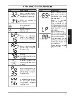
Page 10: ...r 03 General lockout Er 04 Faulty primary circuit no water or absence of flow Er 05 Faulty fan control sys tem LCD FUNCTION Er 06 Faulty c h temp probe NTC Er 08 Faulty external temp probe NTC Er 09 F...

Page 11: ...sh every 4 sec Pump activated for the post circulation phase Po flashing tempera ture flashing Delayed burner ignition for setting the system uu flashing tempera ture flashing LCD FUNCTION Maintenance...

Page 12: ...to access the INFO menu The display displays the value d0 that alter nates with the pressure value 13 1 3 bar The number indicating the pressure is dis played without decimal points while the let ter...

Page 13: ...nt air from your radia tor circuit using your radiator key however be aware that excessive venting will cause the pressure in the system to drop Always ensure that the pressure gauge is set at the req...

Page 14: ...the external temperature probe option al fitted Adjust the c h water flow as follows from 25 to 35 with an external tempera ture included between 5 and 15 C from 35 to 60 with an external tempera tur...

Page 15: ...ed or reduced by 15 C by acting on keys 12 reduce and 13 increase Fig 2 5 2 5 Extinguishing Press the key for 2 seconds 11 Fig 2 9 un til the symbol appears on the display Fig 2 10 Fig 2 9 11 12 13 14...

Page 16: ...not lit and used in cold weather with consequent risk of freezing do not switch off the boiler at the fused spur isolation switch or close the gas inlet cock If the boiler is deactivated have a qualif...

Page 17: ...ates that the safety lock out has stopped the boiler The display background flashes Fig 3 3 Fig 3 3 RESET RESET For the first lighting up and following mainte nance procedures for the gas supply it ma...

Page 18: ...happen and to decrease the pressure to a normal value it is advisable to vent some of the water in the ap pliance through the bleed valves present in the radiators Water should occasionally leak from...

Page 19: ...obe NTC 09E Flue probe intervention lock out 10E Flame detection error 11E No circulation of faulty pump or intervention primary tem perature limit 14E 3 9 Flue probe The flue probe 15 and safety ther...

Page 20: ...20 INSTALLATION TECHNICAL INFORMATION 4 TECHNICAL INFORMATION 4 1 Overview Fig 4 1 15 17 35 19 21 16 18 32 29 36 34 31 23 24 25 26 30 33 28 27 38 39 20...

Page 21: ...15 Flue temperature probe NTC 16 C h temperature probe NTC 17 Condensing heat exchanger 18 Safety thermostat 19 Condensing heat exchanger air purger valve 20 Safety thermal fuse 21 Flame detecting el...

Page 22: ...probe terminal block remote terminal block power supply terminal block external controls terminal block 30 Primary circuit pressure switch 31 Condensate trap 32 Fan 33 Air box air gas mixer 34 Igniti...

Page 23: ...water circulation in the heating plant due to the closing of thermostatic valves or circuit elements valves by pass ensures a minimum water circulation inside the con densing primary exchanger The by...

Page 24: ...bar 0 3 Available head in 1000 l h kPa 23 bar 0 23 Seasonal efficency G20 88 7 Seasonal efficency G31 c 89 7 to the minimum useful output A referred to the net calorific value at 15 C and 1013 25 mbar...

Page 25: ...pipes mm 80 80 Roof mm 80 125 Nominal heat flow rate A E kW 16 0 Exhaust temperature E C 72 0 Mass flow rate E kg s 0 0068 Flue gas figures Nominal heat input A E kW 16 0 CO2 content with gas G20 9 2...

Page 26: ...bar 0 3 Available head in 1000 l h kPa 23 bar 0 23 Seasonal efficency G20 88 8 Seasonal efficency G31 c 89 8 to the minimum useful output A referred to the net calorific value at 15 C and 1013 25 mbar...

Page 27: ...pipes mm 80 80 Roof mm 80 125 Nominal heat flow rate A E kW 25 0 Exhaust temperature E C 83 1 Mass flow rate E kg s 0 0105 Flue gas figures Nominal heat input A E kW 25 0 CO2 content with gas G20 9 0...

Page 28: ...0 bar 0 3 Available head in 1000 l h kPa 27 bar 0 27 Seasonal efficency G20 88 6 Seasonal efficency G31 c 89 6 to the minimum useful output A referred to the net calorific value at 15 C and 1013 25 mb...

Page 29: ...m 80 80 Roof mm 80 125 Nominal heat flow rate A E kW 30 0 Exhaust temperature E C 81 6 Mass flow rate E kg s 0 0127 Flue gas figures Nominal heat input A E kW 30 0 CO2 content with gas G20 9 2 9 8 O2...

Page 30: ...iler and system For Ireland IE it is necessary to com plete a Declaration of Conformity to indicate compliance to I S 813 2002 This appliance must be installed by a competent person in accordance with...

Page 31: ...ace as an outhouse or lean to It is important that the position of the terminal allows a free passage of air across at all times The terminal should be located with due regard for the damage or discol...

Page 32: ...ld be fitted in accord ance with BS 6891 and the complete instal lation should be tested for tightness For Ireland IE refer to I S 813 2002 5 5 Air supply The room in which the boiler is installed doe...

Page 33: ...1 2003 BSEN 14446 2004 the following notes are given for general guidance For Ireland IE refer to I S 813 2002 Pipework Copper tubing to BSEN 1057 is recom mended for water pipes Jointing should be ei...

Page 34: ...ovided and it must comply with local water authority regulations The correct method is shown in Fig 5 4 The temporary connection must be re moved immediately after filling Fig 5 4 Temporary connection...

Page 35: ...use of a fused spur isolation switch Its installation permits a complete switching off in the con ditions of the overvoltage category III Alter natively it can be used a 3A fused three pin plug and un...

Page 36: ...ments of the distribu tors and comply with current Regulations and laws in force The safety relief valve and the condensate drain must be connected to a suitable drain or discharge in a safe manner Th...

Page 37: ...product in the circulating water The latter option in particular not only cleans out the system but also has an anti corrosive effect by promoting formation of a protective skin on metal surfaces and...

Page 38: ...s Pipe sizes o d Gas c h return c h flow 22 Pressure relief valve 15 Condensate drain 25 plastic sizes in mm o d Condensate drain to be realised with min pipe 30 mm 6 6 Mounting the boiler Assemble th...

Page 39: ...For a correct installation of the flue pipe re fer to the sheet provided together with the pre selected kit The horizontal routes of the flue pipes must incline about 1 5 degrees 25 mm per me ter ther...

Page 40: ...of flu The flue exhaust air intake can be installing in the mode C13 C33 C53 C63 Refer to the sheet provided with the pre selected kit in separate packaging The horizontal routes of the flue pipes mus...

Page 41: ...owever the terminal must always ex haust horizontally Additional bends at 45 or 90 Fig 6 8 C Coaxial bends 60 100 mm These bends when used with the pipe re duce the maximum length of the flue pipe by...

Page 42: ...C 25 kW 93 C 35 kW 98 C Maximum recircula tion of CO2 in the suction duct 16 kW 0 97 25 kW 0 95 35 kW 0 95 Roof flue exhaust kit Fig 6 11 Coaxial pipe 80 125 mm with a nominal height of 0 96 m This k...

Page 43: ...d utilising extensions Each additional elbow reduces the overall acceptable length of the flue system as fol lows 45 60 100 mm reduce length by 0 5 m 90 60 100 mm reduce length by 1 m 45 60 mm reduce...

Page 44: ...minals to which the room thermostat must be connected Connect the earth cable yellow green to an effective earth plant The earth cable must be the longest of the electric power supply cables The appli...

Page 45: ...he electric jumper present be tween 1 and 3 when connecting any type of ambient thermostat The electric cables of the ambient thermo stat are inserted between clamps 1 and 3 as in Fig 6 18 or Fig 6 19...

Page 46: ...as in Fig 6 16 Remove the electric jumper between 1 and 3 Be careful not to connect pow ered cables on clamps 1 and 3 The route of the boiler and ambient thermo stat s electric power supply cable or...

Page 47: ...e the component must be con nected to The lower part shows how to realize a sys tem that provides independent timed and thermostatic control of heating and hot wa ter In Fig 6 24 the boiler is permane...

Page 48: ...hermostat C 1 2 8 7 6 GY WH OR GRYE BU 2 3 8 5 7 MAINS 230V a c Switched 3 Amp fused spur L N 2 3 1 Programmer HTG HW OFF HW ON L N 2 1 4 6 7 10 way junction box Valve colour key WH White GRYE Green Y...

Page 49: ...r HTG HW OFF HW ON L N Do not remove room thermostat link Room thermostat A B 4 5 Cylinder thermostat C 1 2 8 7 6 GY WH OR GRYE BU 2 3 8 5 7 MAINS 230V a c Switched 3 Amp fused spur L N 2 3 1 Programm...

Page 50: ...different channels to the voltage ones 230 V since they are powered at a safe ty low voltage and their maximum length must not exceed 20 meters Use the clamps indicated in Fig 6 26 to connect the ext...

Page 51: ...mps flow rate Therefore by means of a hydraulic separa tor the secondary circuit s flow rate is put into circulation only when the relative pump is on When the pump of the secondary is off there is no...

Page 52: ...813 2002 7 2 Electrical installation Preliminary electrical system checks to en sure electrical safety shall be carried out by a competent person i e polarity earth con tinuity resistance to earth and...

Page 53: ...pect the boiler and the system for wa ter tightness and remedy any leaks dis covered Cold flush the system to remove any loose particles and any system debris be fore starting the boiler for the first...

Page 54: ...um gas working pressures connected to a 1 m flue and a gas supply pressure of 20 mbar Any variation in gas supply pressure or flue length may result in the customer experiencing a harmonic noise from...

Page 55: ...of the Benchmark Important after the checks all of the test points must be sealed 7 8 Lighting the boiler Some products incorporate an anti cycling time delay It is normal when first switch ing the b...

Page 56: ...lay back ground flashes Fig 7 10 Fig 7 10 RESET RESET Press the reset key on the boiler control panel 11 Fig 7 8 to reset its functioning For the first lighting up and following main tenance procedure...

Page 57: ...connected If the boiler is NOT equipped with the re mote control optional refer to Fig 7 15 Fig 7 15 External temperature C 20 20 15 10 5 0 5 10 15 20 25 30 40 50 60 70 80 C h flow temperature C K 6...

Page 58: ...12 13 14 Fig 7 18 Scroll the various parameters using keys 12 or 13 until the letters Pr that alternate with code 15 are displayed on the LCD display indicating that parameter 15 Fig 7 19 has been act...

Page 59: ...ce for setting the K coefficient with the remote control connected Act on the programming of the REMOTE control to select the setting of the K coef ficient Electrically feed the boiler by activating t...

Page 60: ...7 26 has been activated Fig 7 26 Press keys 11 and 13 Fig 7 24 at the same time until the value of parameter 11 10 60 seconds Fig 7 27 is displayed on the LCD display Fig 7 27 It is possible to modify...

Page 61: ...r decreased corre sponds to 1 second Fig 7 31 To exit programming press button 7 12 Selecting the reignition fre quency When the boiler functions in normal on off heating mode the minimum time between...

Page 62: ...s to 99 600s using keys 12 or 13 each increase or reduction by a unit on the display corresponds to 6 seconds By pressing key 11 Fig 7 32 confirma tion of the inserted value is obtained Press keys 11...

Page 63: ...alf minutes Each step increased or decreased corre sponds to 2 seconds To modify the programmed SET act on buttons or and wait for the number programmed to flash Fig 7 39 Fig 7 39 To exit programming...

Page 64: ...electric supply isolator Explain the proper use and adjustment of all system controls this will ensure the great est possible fuel economy Explain the function and use of the function selector Explai...

Page 65: ...ith code 01 are displayed on the LCD display indicating that parameter 01 Fig 7 43 has been activated Fig 7 42 11 12 13 Fig 7 43 Scroll the various parameters using keys 12 or 13 until the letters Pr...

Page 66: ...ct setting of this boiler in case of replacement of the main control p c b PARAMETER DIGIT VALUES Boiler type to be updated with the complete range Pr 01 Water sensors configuration Pr 02 Pump speed P...

Page 67: ...LCD display Fig 7 49 Fig 7 49 Press keys 11 and 12 Fig 7 47 at the same time to exit without changing the value return to the parameters list Fig 7 48 Scroll the various parameters using keys 12 or 1...

Page 68: ...and remove the pipe B Fig 8 1 Fig 8 1 A B C Carry out gas conversion by correctly re placing the gas restrictor Fig 8 2 refer ring to the Technical Data section page 24 Advance Plus 16S page 26 Ad van...

Page 69: ...parameter 05 from 00 G20 to 05 G31 which is ok for LPG gas By pressing key 11 Fig 8 3 confirmation of the inserted value is obtained Press keys 11 and 12 Fig 8 3 at the same time to exit without chan...

Page 70: ...tion switch adjacent to the appliance and turn off the gas cock before carrying out any procedures whatsoever for cleaning maintenance opening or dismantling boiler panels The Engineer should complete...

Page 71: ...pring towards the internal side of the boiler and simultaneously push the front case panel D until it is completely hold in place Fig 9 4 step 1 2 Repeat the same operation on the op posite side of th...

Page 72: ...9 7 To help the draining of the primary circuit loose the condensing heat exchanger air purger valve 19 in Fig 9 8 Fig 9 7 24 Fig 9 8 19 9 5 Cleaning the condensing primary exchanger and the burner R...

Page 73: ...into safety lockout Therefore should the insulation be wet or deteriorated provide for the substitution of the same Fig 9 11 If the condensate primary exchanger ele ments are dirty notable only after...

Page 74: ...y sweep function at maximum heating power see Setting the boiler chimney sweep function to page 76 Make sure that the ambient thermostat is in the position call for heat Withdraw an abundant amount of...

Page 75: ...pipe 31 Fig 9 16 does not require any particular mainte nance but just check That no solid deposits have formed if so remove them That the condensate drain piping is not clogged Unscrew the plug to c...

Page 76: ...icating that parameter 01 Fig 9 18 has been activated Fig 9 17 11 12 13 Fig 9 18 Chimney sweep function at minimum output in domestic hot water mode Press keys 12 and 13 Fig 9 17 at the same time unti...

Page 77: ...rated output in heating mode Fig 9 21 Fig 9 21 Chimney sweep function at maximum output Press further key 13 to vary again the output in chimney sweep mode when the LCD display displays the letters dP...

Page 78: ...ect the customer s statutory rights If yes and if required by the manufacturer has a water scale reducer been fitted Condensing Boilers only The condensate drain has been installed in accordance with...

Page 79: ...er Name Company Name Telephone No Gas Safe Register No Comments Signature Date Engineer Name Company Name Telephone No Gas Safe Register No Comments Signature Date Engineer Name Company Name Telephone...

Page 80: ...Biasi UK Ltd Commercial Road Leamore Enterprise Park WALSALL WS2 7NQ Sales Tel 01922 714600 Tech Service Tel 01922 714636 www biasi co uk 1796222010 17962 2201 0 1512 80A5 UK 04 04 2012 N...

Reviews: