- 41 -
INST
ALLA
TION
INSTALLATION
ready angled.
The following kits to be connected to the
boiler are available:
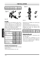
Wall flue exhaust kit (Fig. 6.8 A)
Fig. 6.8
B
A
C
45°
90°
Type C
13
Coaxial pipe Ø 60/100 mm with a nominal
length of 915 mm.
This kit allows the flues to be exhausted in
the rear wall or at the side of the boiler.
The minimum length of the pipe must be no
less than 0.5 m, whilst the maximum with
the aid of extensions must not exceed 10 m.
Vertical flue exhaust kit with 90° bend
(Fig. 6.8 B)
Coaxial pipe Ø 60/100 mm.
This kit allows the boiler exhaust axis to be
lifted by 635 mm.
The length must be no less than 0.5 m,
whilst the maximum with the aid of exten-
sions must not exceed 10 m in horizontal
and however, the terminal must always ex-
haust horizontally.
Additional bends at 45° or 90° (Fig. 6.8 C)
Coaxial bends Ø 60/100 mm.
These bends when used with the pipe re-
duce the maximum length of the flue pipe
by:
For the bend of 45° loss
0,5 m
For the bend of 90° loss
1 m
Exhaust intake split pipes kit Ø 80 mm -
(Fig. 6.9) - (Fig. 6.10)
This kit allows the flue exhaust to be sepa-
rated from the air intake.
The terminals can be inserted in the rele-
vant chimneys planned for such purpose, or
discharge fumes or pick up air directly from
the wall.
N.B: The air intake and the flue outlet
must not terminate on opposite sides of
the building (EN 483).
Fig. 6.9
Type C
13
The minimum length of the pipes must be
less than 0.5 m, whilst the maximum sum
of routes A + B that can be realised with the
aid of extensions must not exceed 40 m.
Bends of Ø 80 mm at 90° and at 45° are
available that reduce the maximum total
length of the pipes by:


