- 8 -
USE
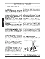
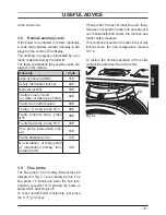
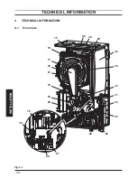
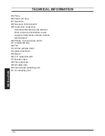
APPLIANCE DESCRIPTION
1
APPLIANCE DESCRIPTION
1.1 Overview
The model and serial number of the boiler
are printed on bottom right side.
Fig. 1.1
1
2
1
Controls panel
2
House for possible time switch
(c.h. control)
1.2 Isolation valves
Fig. 1.2
3
4
5
6
7
8
9
10
*
3
Gas supply label
4
C.h. circuit pressure gauge
5
C.h. flow valve
6
Gas inlet valve
7
C.h. return valve
8
Condensate drain pipe
9
Main circuit drain valve
10
C.h. pressure relief valve pipe
*
model and serial number of the boiler
label.

