background image

- 3 -

W

ARNING

Remember that...

  The manual

 must be read thoroughly, so that you will be able to use the boiler in a safe 

and sensible way; must be carefully kept. It may be necessary for reference in the future.

  The lighting up 

must be carried out by competent and responsible engineer.

  The manufacturer

•  disclaim all liability for any translations of the present manual from which incorrect inter-

pretation may occur;

•  cannot be held responsible for non-observance of instructions contained in this manual 

or for the consequences of any procedure not specifically described.

Please ensure that the installer has fully completed the Benchmark Checklist on the inside 
back pages of the installation instructions supplied with the product and that you have signed 
it to say that you have received a full and clear explanation of its operation. The installer is 
legally required to complete a commissioning checklist as a means of complying with the 
appropriate Building Regulations (England and Wales).
All installations must be notified to Local Area Building Control either directly or through a 
Competent  Persons  Scheme. A  Building  Regulations  Compliance  Certificate  will  then  be 
issued to the customer who should, on receipt, write the Notification Number on the Bench-
mark Checklist.
This product should be serviced regularly to optimise its safety, efficiency and performance. 
The  service  engineer  should  complete  the  relevant  Service  Record  on  the  Benchmark 
Checklist after each service.
The Benchmark Checklist will be required in the event of any warranty.

Using the boiler...

  Before lighting the boiler 

you are advised to have a Gas Safety Registered Engineer 

check that the installation of the gas supply
•  is gas-tight;
•  is of the correct gauge for the flow to the boiler;
•  is fitted with all the safety and control devices required by the current Regulations.

  Ensure that

•  Check with the Installer that he has connected and terminated the pressure relief valve 

in a manner which allows safe discharge. The manufacturers are not responsible for 
damage caused by opening of the pressure relief valve and consequent escape of wa-
ter, if this is not connected and terminated.

•  The installer has connected the condensate outlet to a suitable drain pipe.

Summary of Contents for Advance Plus 25C

Page 1: ...hung fanflue roomsealed high efficiency gas boiler User manual and Installation instructions Advance Plus Models G C Appl No Advance Plus 25C 47 583 29 Advance Plus 30C 47 583 30 Advance Plus 35C 47 5...

Page 2: ...ter systems in the UK and to encourage regular servicing to optimise safety efficiency and performance Benchmark is managed and promoted by the Heating and Hot water Industry Council For more informat...

Page 3: ...otified to Local Area Building Control either directly or through a Competent Persons Scheme A Building Regulations Compliance Certificate will then be issued to the customer who should on receipt wri...

Page 4: ...pply system com patible with its performance and output can be used only for those purposes for which it has been specially designed must not be touched by children or by those unfamiliar with its ope...

Page 5: ...eyes and throat Vapour is harmful Inflammable do not extinguish with water Precautions Do not incinerate Avoid contact with broken leaking phials Do not purposely puncture First aid medical attention...

Page 6: ...t By following this procedure if you have a subsequent problem this method if you have a subsequent problem following the addition of an exter nal control you can eliminate the boiler from your fault...

Page 7: ...7 5 Initial filling of the system 55 7 6 Condensate pipe and traps 57 7 7 Checking the gas supply pressure 57 7 8 Checking the inlet pressure 57 7 9 Lighting the boiler 58 7 10 Enabling functioning of...

Page 8: ...Controls panel 2 House for possible time switch c h con trol 1 2 Isolation valves Fig 1 2 3 4 5 6 7 8 9 10 11 3 Gas supply label 4 C h flow valve 5 D h w outlet valve 6 Gas inlet valve 7 D c w inlet...

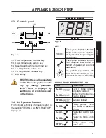
Page 9: ...to the section TECHNICAL INFORMATION to page 23 Fig 1 4 RESET SET C KEY The symbol indicates that the boiler can be directly reactivat ed by the user by pressing the reset button The symbol indicates...

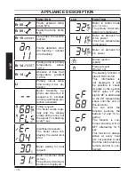
Page 10: ...water lack error Boiler waiting for heat request Boiler in summer mode d h w The primary circuit tem perature is displayed LCD FUNCTION Boiler in winter mode c h d h w The primary circuit tem peratur...

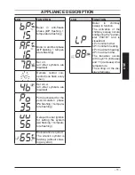
Page 11: ...on phase Po flashing tempera ture flashing Delayed burner ignition for setting the system uu flashing tempera ture flashing Maintenance required The wrench symbol is flashing without show ing any erro...

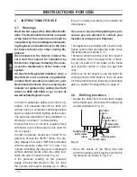
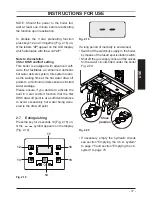
Page 12: ...O menu The dis play displays the value d0 that alternates with the pressure value 13 1 3 bar The number indicating the pressure is displayed without decimal points while the letter indi cates the unit...

Page 13: ...cuit using your radiator key however be aware that excessive venting will cause the pressure in the system to drop Always ensure that the pressure gauge is set at the required pressure 2 3 Ignition Ch...

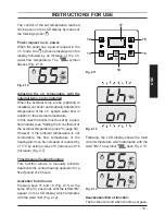
Page 14: ...15 reduce and 16 increase Fig 2 7 from a minimum of about 25 C to a maximum of about 85 C Press one of the two keys once to display the set value Press again to access the modi fication Signal given b...

Page 15: ...fied installer see Setting the K coefficient of the external temperature probe to page 60 However if the ambient temperature is not comfortable the flow temperature of the heating plant can be increas...

Page 16: ...cold water In this way the automatic adjustment fea tures will be appreciated If water hardness is particularly high we rec ommend that the boiler be adjusted to a tem perature less than 50 C In these...

Page 17: ...imited water wastage Please ensure if you decide to activate the built in 3 star comfort function that the first DHW draw off point is at a sufficient distance to avoid excessively hot water being del...

Page 18: ...ler is not lit and used in cold weather with consequent risk of freezing do not switch off the boiler at the fused spur isolation switch or close the gas inlet cock If the boiler is deactivated have a...

Page 19: ...he letter Er and the writing RESET see LCD general features to page 9 appear on the LCD display it in dicates that the safety lock out has stopped the boiler The display background flashes Fig 3 3 Fig...

Page 20: ...as gone down It is necessary to top up the appliance with water again so as to raise the pressure to an adequate level as described in the sec tion Refilling procedure to page 12 of this manual If top...

Page 21: ...keys 14 and 16 Fig 3 6 at the same time until the letter di appears on the display that alternates with a code Fig 3 7 Fig 3 6 12 13 14 15 16 17 Fig 3 7 To scroll the values press 15 reduce and 16 in...

Page 22: ...ue temperature exceeds 110 C placing the boiler in safety block switching it off To reset normal boiler functioning just press the 14 Fig 3 6 key If flue probe 19 does not intervene and therefore does...

Page 23: ...23 INSTALLATION TECHNICAL INFORMATION 4 TECHNICAL INFORMATION 4 1 Overview Fig 4 1 19 22 42 18 24 21 23 39 33 45 41 36 35 26 27 28 29 34 40 38 37 32 31 30 43 48 49 20...

Page 24: ...eturn valve 9 Condensate drain pipe 10 Main circuit drain valve 18 Condensing heat exchanger air purger valve 19 Flue temperature probe NTC 20 Safety thermal fuse 21 C h temperature probe NTC 22 Conde...

Page 25: ...terminal block power supply terminal block external controls terminal block 34 Primary circuit pressure switch 35 Condensate trap 36 D h w heat exchanger 37 Three way diverter valve 38 Three way elec...

Page 26: ...ax flow temperature settings C 25 85 Maximum pressure kPa 250 bar 2 5 Minimum pressure kPa 30 bar 0 3 Available head in 1000 l h kPa 23 0 bar 0 230 Seasonal efficency G20 c 88 7 Seasonal efficency G31...

Page 27: ...atural G20 Fuch sia Fucsia Propane G31 Fuch sia Fucsia Electrical data Voltage V 230 Frequency Hz 50 Power consumption W 102 Protection degree IPX5D External fuse rating A 3 Internal fuse rating A N 2...

Page 28: ...gas G20 range min max 8 7 9 3 CO2 content with gas G31 range min max 9 4 10 4 CO2 contents domestic hot water Nominal heat input A E kW 25 0 CO2 content with gas G20 range min max 9 3 9 9 CO2 content...

Page 29: ...Max flow temperature settings C 25 85 Maximum pressure kPa 250 bar 2 5 Minimum pressure kPa 30 bar 0 3 Available head in 1000 l h kPa 27 0 bar 0 270 Seasonal efficency G20 c 88 7 Seasonal efficency G3...

Page 30: ...ictors Natural G20 Blue Blu Propane G31 Blue Blu Electrical data Voltage V 230 Frequency Hz 50 Power consumption W 130 Protection degree IPX5D External fuse rating A 3 Internal fuse rating A N 2 2 AF...

Page 31: ...gas G20 range min max 8 7 9 3 CO2 content with gas G31 range min max 9 4 10 4 CO2 contents domestic hot water Nominal heat input A E kW 30 0 CO2 content with gas G20 range min max 9 2 9 8 CO2 content...

Page 32: ...in Max flow temperature settings C 25 85 Maximum pressure kPa 250 bar 2 5 Minimum pressure kPa 30 bar 0 3 Available head in 1000 l h kPa 27 0 bar 0 270 Seasonal efficency G20 c 88 6 Seasonal efficency...

Page 33: ...ctors Natural G20 Blue Blu Propane G31 Blue Blu Electrical data Voltage V 230 Frequency Hz 50 Power consumption W 135 Protection degree IPX5D External fuse rating A 3 Internal fuse rating A N 2 2 AF F...

Page 34: ...gas G20 range min max 8 7 9 3 CO2 content with gas G31 range min max 9 4 10 4 CO2 contents domestic hot water Nominal heat input A E kW 34 0 CO2 content with gas G20 range min max 9 3 9 9 CO2 content...

Page 35: ...f water circulation in the heating plant due to the closing of thermostatic valves or circuit elements valves by pass ensures a minimum water circulation inside the con densing primary exchanger The b...

Page 36: ...eland IE it is necessary to com plete a Declaration of Conformity to indicate compliance to I S 813 2002 This appliance must be installed by a competent person in accordance with the Gas Safe installa...

Page 37: ...t the position of the terminal allows a free passage of air across at all times The terminal should be located with due regard for the damage or discoloration that might occur to building products in...

Page 38: ...the complete instal lation should be tested for tightness For Ireland IE refer to I S 813 2002 5 5 Air supply The room in which the boiler is installed does not require a purpose provided air vent 5 6...

Page 39: ...es are given for general guidance For Ireland IE refer to I S 813 2002 Pipework Copper tubing to BSEN 1057 is recom mended for water pipes Jointing should be either with capillary soldered or with com...

Page 40: ...kely that the mains domestic water pressure may exceed 5 bar it is possible due to internal water hammer effects that the pressure within the domestic system can increase to a level in excess of the 1...

Page 41: ...s of the local water company 5 11 Electrical supply Warning this appliance must be earthed External wiring to the appliance must be carried out by a competent person and be in accordance with the curr...

Page 42: ...ments of the distribu tors and comply with current Regulations and laws in force The safety relief valve and the condensate drain must be connected to a suitable drain or discharge in a safe manner Th...

Page 43: ...product in the circulating water The latter option in particular not only cleans out the system but also has an anti corrosive effect by promoting formation of a protective skin on metal surfaces and...

Page 44: ...ensate drain 25 plastic sizes in mm o d Condensate drain to be realised with min pipe 30 mm 6 6 Mounting the boiler Assemble the pre piping kit bracket by screwing the four screws L Fig 6 3 Fix the wa...

Page 45: ...Water circulation c h pag 39 in this manual 6 7 Fitting the flue system For a correct installation of the flue pipe re fer to the sheet provided together with the pre selected kit The horizontal route...

Page 46: ...of flu The flue exhaust air intake can be installing in the mode C13 C33 C53 C63 Refer to the sheet provided with the pre selected kit in separate packaging The horizontal routes of the flue pipes mus...

Page 47: ...owever the terminal must always ex haust horizontally Additional bends at 45 or 90 Fig 6 8 C Coaxial bends 60 100 mm These bends when used with the pipe re duce the maximum length of the flue pipe by...

Page 48: ...C 30 kW 98 C 35 kW 98 C Maximum recircula tion of CO2 in the suction duct 25 kW 0 95 30 kW 0 95 35 kW 0 95 Roof flue exhaust kit Fig 6 11 Coaxial pipe 80 125 mm with a nominal height of 0 96 m This ki...

Page 49: ...d utilising extensions Each additional elbow reduces the overall acceptable length of the flue system as fol lows 45 60 100 mm reduce length by 0 5 m 90 60 100 mm reduce length by 1 m 45 60 mm reduce...

Page 50: ...minals to which the room thermostat must be connected Connect the earth cable yellow green to an effective earth plant The earth cable must be the longest of the electric power supply cables The appli...

Page 51: ...resent be tween 1 and 3 when connecting any type of ambient thermostat The electric cables of the ambient thermo stat are inserted between clamps 1 and 3 as in Fig 6 18 or Fig 6 19 or Fig 6 20 Be care...

Page 52: ...ve the electric jumper between 1 and 3 Be careful not to connect pow ered cables on clamps 1 and 3 The route of the boiler and ambient thermo stat s electric power supply cable or wires must follow th...

Page 53: ...different channels to the voltage ones 230 V since they are powered at a safe ty low voltage and their maximum length must not exceed 20 meters Use the clamps indicated in Fig 6 24 to connect the ext...

Page 54: ...mps flow rate Therefore by means of a hydraulic separa tor the secondary circuit s flow rate is put into circulation only when the relative pump is on When the pump of the secondary is off there is no...

Page 55: ...be carried out by a competent person i e polarity earth con tinuity resistance to earth and short circuit If a fault has occurred on the appliance the fault finding procedure should be followed as spe...

Page 56: ...pect the boiler and the system for wa ter tightness and remedy any leaks dis covered Cold flush the system to remove any loose particles and any system debris be fore starting the boiler for the first...

Page 57: ...gas working pressures connected to a 1 m flue and a gas supply pressure of 20 mbar Any variation in gas supply pressure or flue length may result in the customer experiencing a harmonic noise from th...

Page 58: ...e test points must be sealed 7 9 Lighting the boiler Some products incorporate an anti cycling time delay It is normal when first switching the boiler on for the boiler to operate on heat ing for a fe...

Page 59: ...will light If after four ignition attempts about four minutes the boiler does not function and a code that alternates between the letter Er and the writing RESET appear on the LCD display it indicate...

Page 60: ...Press buttons and at the same time to enter the transparent programming Fig 7 12 Fig 7 12 Press buttons or to display the PM15 program that enables the ex ternal probe Fig 7 13 Fig 7 13 Modify the pro...

Page 61: ...nal probe it is nec essary to set this parameter based on the efficiency of the heating plant in order to op timise the flow temperature Fig 7 16 E g In order to have a flow temperature at the heating...

Page 62: ...seconds to exit the pro gramming mode At this point the plant flow temperature will follow the trend in relation to the K coeffi cient set However if the ambient temperature is not comfortable the flo...

Page 63: ...ged by a minimum of zero to a maximum of four minutes by act ing on programming both from the panel controls and the remote control Enter in programming mode by pressing keys 14 15 16 Fig 7 24 for 10...

Page 64: ...nfirma tion of the inserted value is obtained Press keys 14 and 15 Fig 7 24 at the same time to exit without changing the value return to the parameters list Fig 7 26 Press keys 14 15 16 Fig 7 24 at t...

Page 65: ...e can be changed by a minimum of zero to a maximum of eight and a half min utes by acting on programming both from the panel controls and the remote control Enter the programming mode by press ing key...

Page 66: ...Fig 7 34 Press keys 14 15 16 Fig 7 32 at the same time for 10 seconds to exit the pro gramming mode Programming using the REMOTE con trol Act on the programming of the REMOTE control to select a mini...

Page 67: ...s and fixing are secure and tight Ensure that the flue terminal is sited cor rectly in accordance with the flue fitting in structions and Fig 5 1 on page 37 of this manual To carry out a combustion ch...

Page 68: ...year The user is responsible for keeping the documentation integral and within reach for consultation 7 18 Adjustment of useful c h output The following procedure allows the output of the boiler for c...

Page 69: ...he correct Value ap pertaining to the output required for the central heating requirement By pressing key 14 Fig 7 42 confirma tion of the inserted value is obtained Press keys 14 and 15 Fig 7 42 at t...

Page 70: ...used Pr 21 Not used Pr 22 Not used Pr 23 Not used Pr 24 Not used Pr 25 Not used Pr 26 C h minimum set point Pr 27 Maintenance inter vals Pr 28 NTC inlet probe Pr 29 Correct pressure c h system Pr 30...

Page 71: ...hat alternate with code 02 are displayed on the LCD display indicating that parameter 02 has been activated Repeat all the above setting sequences in order to visualize the parameters and their values...

Page 72: ...and remove the pipe B Fig 8 1 Fig 8 1 A B C Carry out gas conversion by correctly re placing the gas restrictor Fig 8 2 refer ring to the Technical Data section page 26 Advance Plus 25C page 29 Ad van...

Page 73: ...of parameter 05 from 00 G20 to 05 G31 which is ok for LPG gas By pressing key 14 Fig 8 3 confirmation of the inserted value is obtained Press keys 14 and 15 Fig 8 3 at the same time to exit without ch...

Page 74: ...tion switch adjacent to the appliance and turn off the gas cock before carrying out any procedures whatsoever for cleaning maintenance opening or dismantling boiler panels The Engineer should complete...

Page 75: ...ng towards the internal side of the boiler and simultaneously push the front case panel D until it is completely hold in place Fig 9 4 step 1 2 Repeat the same operation on the op posite side of the f...

Page 76: ...ve 10 To make draining easier lift the plug 27 of the automatic relief valve in Fig 9 7 To help the draining of the primary circuit loose the condensing heat exchanger air purger valve 18 in Fig 9 8 F...

Page 77: ...it sends the boiler into safety lockout Therefore should the insulation be wet or deteriorated provide for the substitution of the same Fig 9 11 If the condensate primary exchanger ele ments are dirty...

Page 78: ...commended that a combustion analy sis check is made Remove the plug as indi cated in Fig 9 12 and carry out combustion analysis check and adjustment if necessary as described in the section Gas valve...

Page 79: ...sts with a an 80 mm double exhaust split by 1 1 m and natural gas G20 and a supply return heating temperature of 60 80 C The values in the tables are measured at the nominal useful power with factory...

Page 80: ...0 seconds at the same time until the letters Pr that al ternate with code 01 are displayed on the LCD display indicating that parameter 01 Fig 9 18 has been activated Fig 9 17 12 13 14 15 16 Fig 9 18...

Page 81: ...entually range rated output in heating mode Fig 9 21 Fig 9 21 Chimney sweep function at maximum output in domestic hot water mode Press further key 16 to vary again the output in chimney sweep mode wh...

Page 82: ...ect the customer s statutory rights If yes and if required by the manufacturer has a water scale reducer been fitted Condensing Boilers only The condensate drain has been installed in accordance with...

Page 83: ...er Name Company Name Telephone No Gas Safe Register No Comments Signature Date Engineer Name Company Name Telephone No Gas Safe Register No Comments Signature Date Engineer Name Company Name Telephone...

Page 84: ...Biasi UK Ltd Commercial Road Leamore Enterprise Park WALSALL WS2 7NQ Sales Tel 01922 714600 Tech Service Tel 01922 714636 www biasi co uk 1796221990 17962 2199 0 1512 84A5 UK 04 04 2012 N...

Reviews: