- 51 -
INST
ALLA
TION
INSTALLATION
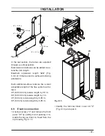
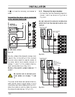
Allow the cables to exit the boiler by using
the relevant cable clamps Y (Fig. 6.17).
Fig. 6.17
Y
6.10 Connecting the room thermo-
stat or zone valves
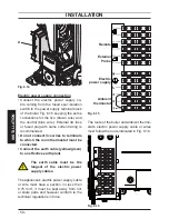
Use the clamps indicated in Fig. 6.15 to
connect the ambient thermostat.
Remove the electric jumper present be-
tween “1 and 3” when connecting any
type of ambient thermostat.
The electric cables of the ambient thermo-
stat are inserted between clamps “1 and 3”
as in Fig. 6.18 or Fig. 6.19 or Fig. 6.20.
Be careful not to connect pow-
ered cables on clamps “1 and
3”.
Fig. 6.18
1
T
Potential clean contacts
of the Ambient
Thermostat
Fig. 6.19
N
L
3
2
1
Room thermostat
(230V rating)
T
Fig. 6.20
Room thermostat
1
2
3
L
N
with delay resistor
(230V rating)
T
The thermostat must be insulation class

