background image

- 35 -

INST

ALLA

TION

INSTALLATION

CORRECT 

implementation 

of 

wall-mounted concentric discharge sys

-

tem

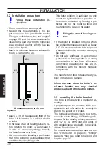
Figure 5.5

A+S

ASA

A

 = air suction

S

 = flue gas outlet

CORRECT  implementation  of  twin  flue 

gas outlet/air suction systems

Figure 5.6

S

S

A

A

 = air suction

S

 = flue gas outlet

INCORRECT implementation of twin flue 

gas outlet/air suction systems

Figure 5.7

S

A

S

A

 = air suction

S

 = flue gas outlet

5.8  Flue gas outlet dimensions and 

lengths

The flue gas outlet/air suction can be set up 

in the following ways:

C

13

 C

33

 C

43

 C

53

 C

63

 C

83

 C

93

 B

23P

Consult the sheet provided with the select-

ed kit which is packaged separately.

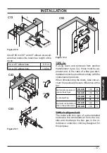
The horizontal sections of the flue gas pipes 

must have a slope of approx. 1.5 degrees 

(25 mm per metre).

The  terminal  must  be  higher 

than the boiler side opening.

Only the coaxial pipe with the terminal must 

be horizontal as the discharge pipe has al-

ready been implemented with the correct 

Summary of Contents for Basica Cond 25S

Page 1: ...User manual and installation instructions Basica Cond...

Page 2: ...le for failure to observe the instructions contained in this manual or the consequences of any actions that have not been specifically described DURING INSTALLATION After removing the packaging make s...

Page 3: ...te sparks Immediately open up the doors and windows to create an air current that cleans the room Close the gas cocks Request the intervention of professionally qualified personnel Before starting the...

Page 4: ...nnot be considered as a contract with third parties DANGER Instructions marked with this symbol must be observed to prevent mechanical or generic accidents e g injuries or bruises DANGER Instructions...

Page 5: ...14 Enabling of operation with remote control optional 43 5 15 Installing the external temperature sensor 44 5 16 Electrical connection between the boiler and the external sensor 44 5 17 Enabling opera...

Page 6: ...e figures in this manual only show one of the possible ways of installing cocks pipes and fit tings Figure 1 2 2 3 4 5 6 7 8 9 12 11 10 2 Gas supply label 3 Condensate outlet pipe 4 Heating circuit fi...

Page 7: ...stics For the boiler technical specifications con sult the section TECHNICAL SPECIFICA TIONS on page 18 Figure 1 4 bar RESET KEY The symbol indicates a volatile error The boiler is reactivated automat...

Page 8: ...are disabled LCD FUNCTION E04 Pump circulation failure or insufficient system pressure E05 Fan control anomaly E06 Heating NTC probe fail ure E07 DHW NTC probe fail ure E08 External NTC probe failure...

Page 9: ...CRIPTION LCD FUNCTION Boiler in chimney sweep function To activate the chim ney sweep function set parameter P06 0 1 minimum power 2 maximum power During the the chimney sweep function the and or symb...

Page 10: ...in section Antifreeze protec tion on page 14 2 2 Ignition The boiler cocks and the cocks used during installation must be open Figure 2 1 Figure 2 1 Open position Power the boiler by turning on the t...

Page 11: ...eating delivery hot water temperature and the symbol flash The display background lights up Figure 2 7 Figure 2 7 bar RESET Adjusting the heating temperature based on the outdoor temperature without e...

Page 12: ...s is pressed the set value is displayed The second time it is pressed the value can be changed Signal on the LCD display the set value of the domestic hot water and the symbol flash The display backgr...

Page 13: ...bar RESET In OFF mode the antifreeze protection is active If the boiler will be inactive for a long period of time disconnect the boiler from the electric power supply close the boiler cocks Figure 2...

Page 14: ...m thermostat is installed If a radiator or convector does not heat up check if there is any air in the system and make sure that the cock is open If the room temperature is too high do not adjust the...

Page 15: ...an error code flashes on the display and the symbol is shown it is a volatile lockout The boiler is reactivated automatically once the fault has been resolved see General LCD char acteristics on page...

Page 16: ...down the boiler as de scribed in section Shutdown on page 13 and call a techni cian from the authorised service centre 3 7 Displays in INFO mode INFO mode is used to view boiler status in formation In...

Page 17: ...Flue thermal fuse Tripping of the flue gas thermal fuse involves a safety lockout and requires resetting by an Au thorised Service Centre The flue thermal fuse 20 indicated in Figure 3 9 is a safety d...

Page 18: ...18 INSTALLATION TECHNICAL SPECIFICATIONS 4 TECHNICAL SPECIFICATIONS 4 1 Assembly view Figure 4 1 20 22 40 23 21 37 31 4 33 34 36 36 35 28 41 30 12 25 10 24 26 32 27 11 38 39 45 46 42...

Page 19: ...ock 8 Domestic hot water inlet pipe 9 Heating return pipe 10 Heating circuit safety valve discharge pipe 11 Heating circuit drain cock 12 Heating circuit pressure gauge 20 Flue thermal fuse 21 Heating...

Page 20: ...remote control optional elec tric power supply cable 32 Heating pressure switch 33 Condensate discharge siphon 34 DHW exchanger 35 Three way valve 36 Three way valve plug 37 Fan 38 Air gas mixer 39 A...

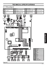
Page 21: ...V r c b b b t b b c c n n n n n n t r r r r b m b m c m n n 2 5 7 8 9 10 11 12 1 3 4 6 a orange b white c blue g yellow gr grey m brown n black r red v purple g v yellow green 1 Electrical power suppl...

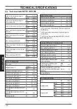
Page 22: ...with G31 9 4 10 0 Condensate quantity at nom Q 30 50 C l h 4 2 Condensate quantity at min Q 30 50 C l h 0 8 Condensate pH l h 4 0 Data in d h w mode CO2 at nom Q with G20 9 1 9 7 CO2 at min Q with G20...

Page 23: ...nimum useful power Domestic hot water Temp Minimum Maximum C 35 60 Maximum pressure kPa 1000 bar 10 Minimum pressure kPa 30 bar 0 3 Maximum flow rate T 25 K l min 14 7 T 35 K l min 10 3 Minimum flow r...

Page 24: ...bient temperature C n a Max ambient temperature C n a Flue gas discharges Boiler type B23P C13 C33 C43 C53 C63 C83 C93 Coaxial air flue gas duct mm 60 100 Twin pipe air flue gas duct mm 80 80 Coaxial...

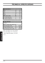
Page 25: ...rated heat output and low temperature regime 1 96 8 Auxiliary electricity consumption Other items At full load elmax 0 033 kW Standby heat loss Pstby 0 110 kW At part load elmin 0 013 kW Ignition bur...

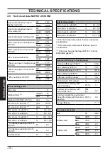
Page 26: ...with G31 9 4 10 0 Condensate quantity at nom Q 30 50 C l h 4 8 Condensate quantity at min Q 30 50 C l h 1 2 Condensate pH l h 4 0 Data in d h w mode CO2 at nom Q with G20 9 1 9 7 CO2 at min Q with G20...

Page 27: ...useful power Domestic hot water Temp Minimum Maximum C 35 60 Maximum pressure kPa 1000 bar 10 Minimum pressure kPa 30 bar 0 3 Maximum flow rate T 25 K l min 17 6 T 35 K l min 12 3 Minimum flow rate l...

Page 28: ...mbient temperature C n a Max ambient temperature C n a Flue gas discharges Boiler type B23P C13 C33 C43 C53 C63 C83 C93 Coaxial air flue gas duct mm 60 100 Twin pipe air flue gas duct mm 80 80 Coaxial...

Page 29: ...rated heat output and low temperature regime 1 97 2 Auxiliary electricity consumption Other items At full load elmax 0 037 kW Standby heat loss Pstby 0 110 kW At part load elmin 0 012 kW Ignition bur...

Page 30: ...losure of thermostatic valves or circuit cocks the by pass guarantees a min imum circulation of water inside the primary condensate exchanger The by pass is calibrated for a differential pressure of a...

Page 31: ...and gas supply networks comply with those on the plate The combustion products may only be dis charged using the flue gas exhaust kits pro vided by the manufacturer as they are an integral part of th...

Page 32: ...etal surfaces and neutralising the gases in the water Filling the central heating sys tem If the boiler is installed in rooms where the ambient temperature could fall below 0 C it is recommended to ta...

Page 33: ...ir suction 80 twin pipe D Boiler mounting bracket E Area for positioning the electric connec tion channels F Area for positioning the condensate outlet pipe G MR Heating delivery H US DHW output I Gas...

Page 34: ...should be installed in order to disconnect the system for maintenance purposes Block the pipes by placing 1 2 and 3 4 gaskets between the boiler fittings Carry out a leakage test for the gas supply s...

Page 35: ...S A S A air suction S flue gas outlet 5 8 Flue gas outlet dimensions and lengths The flue gas outlet air suction can be set up in the following ways C13 C33 C43 C53 C63 C83 C93 B23P Consult the sheet...

Page 36: ...elbows 60 100 mm When these elbows are used in the duct they reduce the maximum length of the flue gas duct by For a 45 elbow loss 0 5 m For a 90 elbow loss 1 m Twin pipe suction outlet duct kit 80 mm...

Page 37: ...gas duct materials must be used that comply with the condensation products When dimensioning the ducts take into ac count the residual pressure difference at the fan Useful static pressure at nominal...

Page 38: ...the ducts by For a 45 elbow loss 0 5 m For a 90 elbow loss 1 m TYPE B23P Figure 5 15 This type of flue gas outlet extracts the nec essary combustion air from the same room as the boiler is installed i...

Page 39: ...nce only Collective exhaust flues can not be used and the output from extractor hoods above cooking appliances of any kind or output from other generators cannot be conveyed through the same flue or f...

Page 40: ...tional or local regu lations Position of the terminal mm A Under the window or other opening 600 B Next to a window or door 400 B Next to an air vent or ventilation opening 600 C Side of a balcony 100...

Page 41: ...by pulling it towards you Figure 5 18 Figure 5 18 L L M N Unscrew the screw N Figure 5 18 and turn the control panel O as shown in Fig ure 5 19 To access the electric power supply remote and external...

Page 42: ...tive earthing system Figure 5 20 Electric power supply TA The earth wire must be longer than the electric power wires The unit s electric power supply cable or wire must have a minimum section of 0 75...

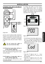
Page 43: ...igure 5 21 to con nect the remote 5 14 Enabling of operation with re mote control optional The boiler leaves the factory with a room thermostat enabled To change this setting to remote control enter p...

Page 44: ...s or walls where mould forms Installation near fans drain outlets or chimneys 5 16 Electrical connection between the boiler and the external sen sor To connect the external sensor to the boiler use el...

Page 45: ...5 K 1 0 K 1 5 K 2 0 K 2 5 K 3 0 K A52 30 25 20 15 10 5 0 5 10 15 20 Figure 5 30 External temperature C 45 50 55 60 65 70 75 80 85 Delivery temperature C 50 80 C 30 25 20 15 10 5 0 5 10 15 20 K 0 2 K...

Page 46: ...ients Press 13 or 14 Figure 5 31 to confirm the value entered and return to the list of pa rameters Figure 5 35 Press the 18 button Figure 5 31 to exit programming mode At this point the system delive...

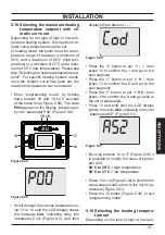
Page 47: ...bar RESET Scroll through the various parameters us ing 13 or 14 until the LCD display shows the message Cod indicating entry into parameter Cod Figure 8 5 and then displays three dashes Figure 5 40 ba...

Page 48: ...13 to confirm the 9 and go to the next segment Press the 17 button to set 1 9 8 then press 13 to confirm the 8 and go back to the list of parameters Press 13 and hold until the LCD display shows the c...

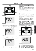
Page 49: ...nd return to the list of pa rameters Figure 5 48 Press the 18 button Figure 5 46 to exit programming mode 5 21 Selecting re ignition frequency When the boiler functions in normal on off heating mode t...

Page 50: ...tor creates a reduced load loss zone that makes the primary cir cuit and secondary circuit hydraulically in dependent In this case the flow rate that passes through the circuits depends exclusively on...

Page 51: ...aulic systems High temperature zone low temperature zone Figure 5 54 S High temp zone Low temp zone External temp probe High temperature zone 2 low temperature zones Figure 5 55 S Low temp zone 1 Low...

Page 52: ...e front panel on the body see section Removing the body panels on page 61 Open the installed water cocks Open one or more hot water cocks to bleed the pipes Loosen the automatic bleed valve cap 25 in...

Page 53: ...symbols and appear on the dis play Figure 6 6 13 14 15 16 17 18 19 The LCD display shows the stand by status and the and symbols Figure 6 7 Figure 6 7 bar RESET Open the gas cock Make sure that the a...

Page 54: ...ON FOR SERVICE Show the user how to use the appliance correctly and also explain ignition shut off making adjustments The user is responsible for keeping the documentation together and intact and with...

Page 55: ...are the value read with those shown in the gas supply pressure table in section Technical data M270V 2025 SM on page 22 and Technical data M270V 2530 SM on page 26 Fully close the tapping point 29 in...

Page 56: ...e gas analyser with the one in the Data in DHW mode table and the val ues of CO2 at Q min section Technical data M270V 2025 SM on page 22 and Technical data M270V 2530 SM on page 26 If the boiler star...

Page 57: ...mming mode Figure 7 13 Figure 7 13 bar RESET Compare the value of CO2 read on the flue gas analyser with the CO2 value at Q nom in DHW mode as stated in section Technical data M270V 2025 SM on page 22...

Page 58: ...igure 7 14 bar RESET During the operations to check maximum and minimum pressure at the burner check the flow rate of gas to the meter and com pare its value with the gas flow rate data see section Te...

Page 59: ...1 Unscrew the swivel joint B and remove the gas pipe A Figure 8 1 Figure 8 1 A B Convert the type of gas by correct ly replacing the gas diaphragm Figure 8 2 referring to section Technical data M270V...

Page 60: ...s The code A01 appears on the display in dicating entry into parameter A01 Fig ure 8 6 Figure 8 6 bar RESET By using buttons 16 or 17 Figure 8 3 it is possible to modify the value of parameter A01 Fig...

Page 61: ...boiler operation problems will not be covered by the standard warran ty Before performing any cleaning or mainte nance operation or before opening or re moving the boiler panels isolate the unit from...

Page 62: ...m s DHW cocks 9 4 Emptying the heating circuit Close the installed heating system deliv ery and return cocks Loosen the heating circuit drain cock 11 indicated in Figure 9 4 Figure 9 4 OPEN CLOSED Hea...

Page 63: ...the fan connector N by press ing the plastic hook O located below the connector Figure 9 6 Loosen the nuts L and remove the fan burner unit 40 Figure 9 6 Extract the burner casing by pulling it out w...

Page 64: ...ing the gas pipe swivel joint 9 6 Check the pressure in the heat ing expansion tank Empty the heating circuit as described in section Emptying the heating circuit on page 62 and check that the expansi...

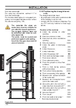
Page 65: ...ition of CO fumes ppm 225 Flue gas temperature C 69 Values refer to tests with 80 mm 1 1 m twin pipe discharge and Methane gas G20 and with heating delivery return temperature of 60 80 C Figure 9 12 M...

Page 66: ...at the same time Figure 9 14 The code P00 appears on the display indicating en try into parameter P00 Figure 9 15 Figure 9 14 13 14 16 17 18 19 Figure 9 15 bar RESET Chimney sweep function at minimum...

Page 67: ...the chimney sweeper reset the value of parameter P06 to 00 or wait 15 minutes with the boiler off OFF Turn the boiler off by pressing the 18 but ton Figure 9 14 until the message OFF appears on the LC...

Page 68: ...to the list of pa rameters Figure 9 24 Press the 18 button Figure 9 21 to exit programming mode Enter programming mode by holding down buttons 18 and 19 for 5 seconds at the same time Figure 9 21 The...

Page 69: ...re 9 21 it is possible to modify the value of param eter A02 01 high temperature 50 80 C 02 low temperature 28 55 C Press 13 or 14 Figure 9 21 to confirm the value entered and return to the list of pa...

Page 70: ...erials where possible The installer must dispose of the packaging used to transport the boiler Please observe the regulations currently in force regarding re cycling and disposing of the boiler and an...

Page 71: ......
Page 72: ...time and without notice Product warranty pursuant to Leg Decree no 24 2002 BSG Caldaie a Gas S p a Registered office sales and administrative headquarters plant and technical support 33170 PORDENONE I...

Reviews: