background image

10

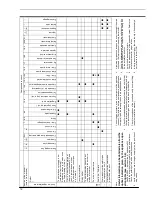
C

om

po

ne

nt

s

to

ch

ec

k

S

ec

tio

n

of

th

e

m

an

ua

l

!

(n

ot

e

re

f.

in

br

ac

ke

ts

)

---

---

--- (8

)

--- (7

)

21

.1

20

.2

19

.2

18

.2

17

16

.2

15

.5

13

.2

12

.4

11

.2

10

.8

9.

2

8.

2

7

--- (4

)

22

.1

--- (3

)

--- (2

)

--- (1

)

Loc

k---

out

sig

nal

lam

pre

d

Pre

ssu

re

gau

ge

Saf

ety

val

ve

Exp

ans

ion

ves

sel

Inj

ect

ors

Flu

eth

erm

ost

at

Saf

ety

the

rm

ost

at

Det

ect

ion

ele

ctro

de

Ign

itio

ne

lec

tro

de

Air

pre

ssu

re

sw

itc

h

Fan

and

ven

tur

id

evi

ce

By-

- -p

ass

val

ve

D.h

.w

.te

mp.

pro

be

Mai

nc

irc

uit

tem

p.p

rob

e

D.h

.w

.fi

lte

r

Mai

nc

irc

uit

flo

ws

witc

h

Gas

val

ve

(m

odu

lat

ing

ope

rat

or)

Gas

val

ve

(on

- --o

ffo

per

ato

rs)

Ful

ls

equ

enc

ed

evi

ce

Fun

ctio

ns

ele

cto

rs

(re

g.p

.c.

b)

Reg

ula

tio

np

.c.

b.

Fus

e(r

egu

lat

ion

p.c

.b.

)

D.h

.w

.fl

ow

sw

itc

h

Div

erte

rv

alv

e

Pum

p

D.h

.w

.h

eat

exc

han

ger

D.h

.w

.c

irc

uit

C.h

.c

irc

uit

Con

den

sat

ed

rai

np

ipe

and

tra

p

Flu

ep

ipe

s

Gas

sup

ply

lin

e

Pow

ers

upp

ly

lin

e

D

ef

ec

t

#

Th

e

bo

ile

rd

oe

s

no

ts

up

pl

y

d.

h.

w

.

(c

ol

d

w

at

er

fro

m

th

e

ta

p)

.

R

eg

ul

ar

op

er

at

io

n

in

c/

h

m

od

e

ev

en

du

rin

g

a

dr

aw

in

g

of

fd

.h

.w

.

J

J

J

O

n

c/

h

m

od

e

th

e

te

m

pe

ra

tu

re

of

th

e

m

ai

n

ci

rc

ui

tr

ea

ch

es

75

°

C

an

d

th

e

c/

h

sy

st

em

do

es

no

th

ea

t.

Th

e

bo

ile

ro

pe

ra

te

s

co

rr

ec

tly

on

d.

h.

w

.m

od

e.

J

J

In

co

rr

ec

tm

od

ul

at

io

n

J

J

J

N

oi

sy

bo

lie

r

J

J

Th

e

bo

ile

ro

pe

ra

te

s

co

rr

ec

tly

bu

t

th

e

ga

s

pr

es

su

re

to

th

e

bu

rn

er

re

-

m

ai

ns

at

m

in

im

um

.

J

J

F

Po

or

d.

h.

w

.t

em

pe

ra

tu

re

J

J

J

J

J

(9

)

OFF

Lo

w

d.

h.

w

.f

lo

w

ra

te

J

J

J

---

W

at

er

le

ak

s

fro

m

th

e

sa

fe

ty

va

lv

e

du

rin

g

op

er

at

io

n

on

c/

h

J

J

J

J

---

W

at

er

le

ak

s

fro

m

th

e

sa

fe

ty

va

lv

e

w

he

n

th

e

bo

ile

ri

s

of

f.

J

J

J

N

ot

e

U

se

fu

li

nf

or

m

at

io

n

ca

n

be

ob

ta

in

ed

al

so

fr

om

th

e

op

tic

al

in

di

ca

tio

n

gi

ve

n

by

th

e

ap

pl

ia

nc

e

op

er

-

at

io

n

lig

ht

s

(s

ee

se

ct

io

n

10

.4

).

1

C

he

ck

fo

r2

30

V~

be

tw

ee

n

lin

e

(L

)a

nd

ne

ut

ra

l(

N

)

Ve

rif

y

th

e

in

te

gr

ity

of

su

pp

ly

ca

bl

e,

pl

ug

an

d

ex

te

rn

al

fu

se

s.

C

he

ck

th

e

po

la

rit

y

of

lin

e

an

d

ne

ut

ra

lc

on

ne

ct

io

n

2

Ve

rif

y

th

e

so

un

dn

es

s

of

th

e

ga

s

su

pp

ly

pi

pe

,t

he

po

si

tio

n

of

st

op

va

lv

es

.

C

he

ck

th

e

ga

s

pr

es

su

re

at

th

e

in

le

tt

es

tp

oi

nt

of

th

e

ga

s

va

lv

e

(s

ee

se

ct

.1

2.

3)

w

ith

th

e

bo

ile

ra

tr

es

ta

nd

du

rin

g

op

er

at

io

n

an

d

co

m

pa

re

it

w

ith

th

e

va

lu

es

gi

ve

n

on

th

e

in

st

al

la

tio

n

bo

ok

le

t.

3

C

he

ck

fo

rs

ou

nd

ne

ss

an

d

ab

se

nc

e

of

ob

st

ru

ct

io

ns

.V

er

ify

th

at

th

e

flu

e

te

rm

in

al

is

co

rr

ec

tly

in

st

al

le

d

(s

ee

cl

ea

ra

nc

es

)a

nd

en

-

su

re

th

at

ex

ha

us

tg

as

is

no

ts

uc

ke

d

ba

ck

by

th

e

bo

ile

r.

4

C

he

ck

fo

rs

ou

nd

ne

ss

of

th

e

ci

rc

ui

ta

nd

ve

rif

y

its

co

rr

ec

tf

ill

in

g

(s

ee

al

so

in

st

al

la

tio

n

m

an

ua

l).

5

A

ja

m

m

ed

by

---

pa

ss

co

ul

d

ca

us

e

th

e

ov

er

---

he

at

in

g

of

th

e

m

ai

n

ci

rc

ui

ta

nd

th

e

in

te

rv

en

tio

n

of

th

e

sa

fe

ty

th

er

m

os

ta

t.

6

C

he

ck

th

e

m

in

im

um

ga

s

pr

es

su

re

at

th

e

ou

tle

tt

es

tp

oi

nt

of

th

e

ga

s

va

lv

e

(s

ee

se

ct

.1

2.

3)

an

d

co

m

pa

re

it

w

ith

th

e

va

lu

e

gi

ve

n

on

th

e

in

st

al

la

tio

n

bo

ok

le

t.

7

Ve

rif

y

th

e

cl

ea

nn

es

s

of

in

je

ct

or

s.

8

C

he

ck

th

e

pr

es

su

riz

at

io

n

of

th

e

ex

pa

ns

io

n

ve

ss

el

.R

ef

er

to

th

e

in

st

al

la

tio

n

m

an

ua

lf

or

pr

op

er

va

lu

es

.

9

d.

h.

w

.p

re

ss

ur

e

to

o

hi

gh

or

flo

w

ra

te

to

o

hi

gh

.I

fn

ec

es

sa

ry

in

-

se

rt

a

flo

w

ra

te

lim

ite

r(

15

.6

).

Summary of Contents for GARDA HE M96.24SM/B

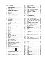
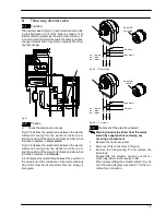
Page 1: ...igh efficiency gas boiler Service manual GARDA HE Models G C Appl No M96 24SM B 47 970 25 M96 28SM B 47 970 26 GARDA HE SILVER Models G C Appl No M96 24SM D 47 970 27 M96 28SM D 47 970 28 Leave this m...

Page 2: ...11 1 Function 23 11 2 Checks 23 11 3 Removal 23 11 4 Ignition and control sequence 24 12 Modulating gas valve 25 12 1 Function 25 12 2 Nomenclature of the parts 25 12 3 Adjustment 25 12 4 Checks 26 12...

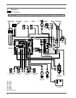
Page 3: ...lease Pump D h w temp probe D h w heat exchanger Expansion vessel Detection electrode valve Condensing Diverter valve Air pressure switch Main circuit Flue thermostat heat exchanger Condensate trap fl...

Page 4: ...A Fig 2 lift the panel and remove it A Fig 2 To remove the side panels loosen the screws B and C Fig 3 bring the base of the panels away from the boiler and lift them freeing them from the top hooks B...

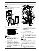
Page 5: ...d of the sealed chamber For this purpose remove the front and side panels of the case remove the screws G as indicated in Fig 6 and remove the lid 2 5 Emptying the primary circuit 1 Close the c h circ...

Page 6: ...low switch C h temperature probe NTC Electronic control p c b Full sequence ignition device gn green ye yellow rd bu wh rd bu rd bu bn bu bn bn bu bn bu bk bn bu 3 1 2 bk gnye bu rd bu bn gnye gnye gn...

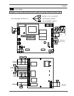
Page 7: ...NTC Three way diverter valve gas valve DHW flow switch flow switch CH temperature probe NTC Electronic control p c b Full sequence ignition device gnye gnye bu gnye gy rd bu wh rd bu rd bu bn bu bn bn...

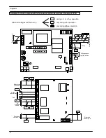
Page 8: ...L Transformer ACTIVE CIRCUIT INACTIVE CIRCUIT L LINE N NEUTRAL N Electronic control p c b low voltage section J1 2 J3 3 J3 5 J3 4 J3 2 J3 1 J2 4 J2 5 Three way diverter valve Pump Full sequence igniti...

Page 9: ...h operation only during d h w operation 230 230 230 0 Pump Full sequence Ignition device 3 way diverter valve 0 0 Electronic control p c b 230 230 Modulating Gas valve Safety thermostat 0 Fan 230 230...

Page 10: ...ration only during d h w operation 230 230 230 0 Pump Full sequence Ignition device 3 way diverter valve 0 0 Electronic control p c b 230 230 Modulating Gas valve Safety thermostat 0 Fan 230 230 0 Ele...

Page 11: ...Pressure gauge By pressing the reset push button the boiler turns on and operates correctly J J 6 J J J By pressing the reset push button the boiler starts the ignition cycle The burner doesn t light...

Page 12: ...e safety valve during operation on c h J J J J Water leaks from the safety valve when the boiler is off J J J Note Useful information can be obtained also from the optical indication given by the appl...

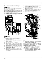
Page 13: ...it from the wiring E M C B F C D G I J N K L H Fig 11 7 Loosen the connection K and move the pipe L downwards freeing it from the connection of the primary het exchanger 8 Remove the clip M 9 Move th...

Page 14: ...see section 21 3 5 Completely loosen the connection G and slightly move the pipe H upwards 6 Remove the clip I and move the pipe J down wards freeing it from the connection then turn it towards right...

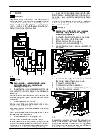
Page 15: ...re removing any covering or component 1 Remove the front and right hand side panels of the case 2 Empty the primary circuit and the d h w circuit of the boiler 3 Completely unscrew the two Allen key s...

Page 16: ...turn the rotor in the direc tion of the arrow If there is a defect in starting the rotor will begin to turn normally only starting it manually n Check that the impeller is integral with the rotor Wit...

Page 17: ...B brass spindle when the boiler operates in c h mode In both figures the relationship between the position of the actuator and the resistance of the motor windings the motor must be disconnected from...

Page 18: ...t both c h and d h w temperature probe respectively H and I 6 Unscrew the connector J the c h flow connector and the d h w outlet connector F G J H I Fig 25 7 Remove the d h w heat exchanger see secti...

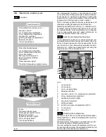
Page 19: ...es inlet in formation coming from the boiler the sensors or from the outside knobs room thermostat etc processes it and consequently acts with outlet commands on other components of the boiler Fig 28...

Page 20: ...trol panel through the adjustment made by the user knob 75 C Fig 31 Normally the result of the comparison between these two signals directly operates the adjustment elements of the gas valve modulatio...

Page 21: ...le to select the various boiler control function modes In Fig 32 the selectors are illustrated in the configur ation in which the boiler is set in the factory natural gas boiler ON 1 OFF 0 1 2 3 4 8 G...

Page 22: ...ectronic control p c b does not supply any de vice pump fan etc check that the fuse 12 Fig 29 is complete If the fuse has blown replace it with one that has the same characteristics after having ident...

Page 23: ...ake sure the c h and d h w tem perature adjustment knobs can move freely for the complete range If not remove the spindle again as described at step 3 turn the knob half a turn and re insert the spind...

Page 24: ...or heat from room thermostat Starts the circulator Operates motorised valve Supplies the ignition device NO Circulator off Operates motorised valve Ignition device off YES YES Fig 40 10 11 Thermal con...

Page 25: ...r connection f Gas injectors blocked f Faulty modulation gas valve faulty on off oper ators or not electrically supplied f Faulty Full sequence ignition device Other components like the air pressure s...

Page 26: ...sure switch at work NO YES starts ignition discharges opens gas valve beginning of ignition period flame presence end of ignition period NO NO YES closes gas valve stops fan interrupts ignition discha...

Page 27: ...e input connect a suitable pressure gauge and check the gas pressure of the supply network 3 Remove the gauge and close the pressure test point 6 4 Open the gas valve outlet pressure test point 8 in F...

Page 28: ...case as explained in the section 2 3 of this manual 2 Disconnect the connector D Fig 47 3 Unscrew the screw E and remove on off oper ator coils 4 Reassemble the coils carrying out the removal operati...

Page 29: ...the switch box verify the position of the shaft B referring to Fig 50 B Boiler OFF Boiler ON Fig 50 n Electrical check It is possible to verify the general operation of the switch by measuring the ele...

Page 30: ...rrect value 14 3 Removal of the expansion vessel If there is at least 400 mm clearance above the boiler and the rear exit flue can be easily removed the expan sion vessel can be changed without removi...

Page 31: ...ssory 10 Threaded ring 1 2 3 4 5 6 7 8 9 10 Fig 59 15 3 Checks Warning isolate the boiler from the mains electricity supply before removing any covering or component n Flow switch sensor operation 1 R...

Page 32: ...tch sensor 1 and bring the ring in touch with the sensor as illustrated in Fig 61 4 Observe the lamp B placed on the sensor body that should light If not reverse the ring and repeat the previous opera...

Page 33: ...flow c h return d h w inlet d h w outlet A B Fig 63 16 2 Checks n Temperature resistance relationship Warning isolate the boiler from the mains electricity supply before removing any covering or compo...

Page 34: ...e is fitted on the rear side of the div erter group A Fig 65 17 2 Removal Warning isolate the boiler from the mains electricity supply before removing any covering or component 1 Remove all the case p...

Page 35: ...measure the electrical resistance of the motor that has to be about 43 W M96 24SM 25 W M96 28SM at ambient temperature D A C Fig 68 n Check of the Air pressure switch operation Warning isolate the bo...

Page 36: ...ls the sealed chamber lid and the combustion chamber lid 2 Disconnect the connectors D and the earth con nection E Fig 68 3 Disconnect the pipe which connect the venturi device to the Air pressure swi...

Page 37: ...manual B H I Fig 73 18 5 Removal of the Air pressure switch Warning isolate the boiler from the mains electricity supply before removing any covering or component 1 Remove all the case panels and the...

Page 38: ...e removing any covering or component 1 Remove all the case panels the sealed chamber lid and the combustion chamber lid 2 Check for the integrity of the insulation of wires which connect the electrode...

Page 39: ...cur Warning isolate the boiler from the mains electricity supply before removing any covering or component n Electrical function 1 Remove all the case panels and the lid of the sealed chamber 2 Remove...

Page 40: ...der a protective cap B in Fig 81 and can be re ached by unscrewing the cap The intervention of the Flue thermostat may be caused by a defective operation of the device but more probably is due to a po...

Page 41: ...ec trode Fig 84 C B Fig 84 If the drain pipe is plugged or in any case in which the condensate isn t correctly evacuated the condensate level in the trap rises putting in contact the electrodes thus c...

Page 42: ...E83 178 Combustion chamber side panels 2 BI1326 100 10 E83 180 Combustion chamber rear panel mod M96 24SM 1 BI1326 107 E83 181 Combustion chamber rear panel mod M96 28SM 1 BI1326 108 11 E83 196 Combus...

Page 43: ...Short spare parts list 41 1 2 6 4 5 7 3 8 15 18 12 13 20 22 23 24 26 27 14 16 25 17 19 9 10 11 9 21...

Page 44: ...796210720 17962 1072 0 2404 44A4 UK Biasi U K Ltd Unit 31 33 Planetary Road Industrial Estate Neachells Lane Willenhall Wolverhampton WV 13 3XB Technical helpline 01902 304 400 Web site www biasi co u...

Reviews: