- 23 -
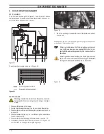
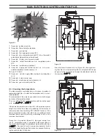
MAIN ElEctroNIc coNtrol/IgNItIoN p.c.b.
figure 9 .10
a
c
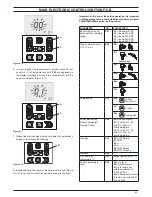
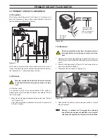
6 In order to pass from a parameter to another press c.h. set
keys (A or C) at the same time until
p 02
are displayed on
the display, indicating the entry in the “parameter 02” and the
value of parameter (Figure 9.11)
figure 9 .11
a
c
7 Repeat the previous steps in order to display the parameter’s
setting or to switch to the following
figure 9 .12
b
To reset the boiler to the normal operation press the key B (Figure
9.5) for 10 second or turn off the electricity supply to the boiler.
important: at the end of the setting operation it is important
to fill/update the table in the installation manual see chapter
cOmmissiOninG section: setting record .
parameter
lcd
values (set)
Boiler type (to be up-
dated with the complete
range)
p 01
00 =
No power Er 99
35
= Inovia 25C ERP
36
= Inovia 30C ERP
37
= Inovia 35C ERP
41
= Inovia 25S ERP
Type of water sensors
(C.h. / d.h.w.)
p 02
00 =
+
+
+
+
01 =
factory set
+
+
+
+
02 =
+
+
+
+
03 =
+
+
+
+
00 =
+
+
+
+
01 =
+
+
+
+
Pump speed
p 03
00 =
(2) Max
factory set
01 =
(1) Med
02 =
Self regulat.
Zone valve setting
Room Thermostat /
Remote Control
p 04
00 =
No (factory set)
01 =
Z1 with R.T., Z2
with R.C., Max. c.h.
flow temperature
02 =
Z1 with R.T., Z2
with R.C., Min. c.h.
flow temperature
Gas type
p 05
00 =
G20 Natural
01 =
G25
02 =
--- --- --- ---
03 =
--- --- --- ---
04 =
G30 Butane
05 =
G31 Propane
Not used
p 06
C.h. flow max
temperature °C
p 07
85÷45
(factory set 85 °C)
Factory parameters
reset
p 08
00 =
No reset
04 =
All parameters
return to factory set
with the exclusion of
P 01 and P 05
39 =
All parameters return
to factory set included Pr
01 and Pr 05
Summary of Contents for Inovia 25C ERP
Page 2: ......

