- 41 -
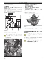
By-pass valve
16 by-pass valve
16 .1 function
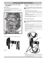
The By-pass valve A in Figure 16.1 is located between the c.h.
water flow and return and its function is that of guaranteeing a
minimum flow across the primary heat exchanger if the circula
-
tion across the c.h. system is completely closed.
The By-pass valve is fitted on the rear side of the diverter group.
figure 16 .1
a
16 .2 removal
warning: isolate the boiler from the mains electrici-
ty supply before removing any covering or compo-
nent .
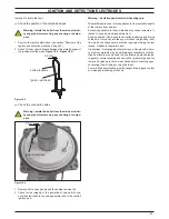
1 Remove all the case panels.
2 Empty the primary circuit of the boiler.
3 Remove the locking plate B and pull up the by-pass valve A
(Figure 16.2).
figure 16 .2
b
a
4 Reassemble the by-pass valve as illustrated in Figure 16.2
reversing the order of removal.
warning: to lubricate the O-ring gaskets exclusively
use a silicone base grease compatible to be in con-
tact with foods and approved by the local water au-
thorities .
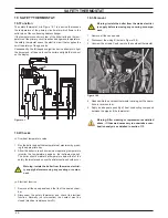
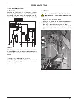
attention . when reassembling the by-pass valve be sure
that it is correctly oriented by matching the reference c with
the notch d of the water group figure 16 .3
figure 16 .3
c
d
a
Summary of Contents for Inovia 25C ERP
Page 2: ......


