- 16 -
THREE WAy DIvERTER vALvE
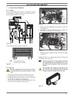
figure 8.4
C
D
E
8.4 Removal of the diverter group and its internal
parts
1 Remove the front and both side case panels.
2 Empty the primary circuit and the d.h.w circuit of the boiler.
3 Remove the electric actuator (section "Removal of the elec-
tric actuator" page 15).
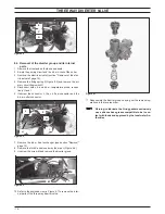
4 Remove the fixing spring F (Figure 8.5) and remove the pri-
mary circuit flow switch G.
5 Disconnect both c.h. and d.h.w. temperature probe, respec-
tively H and I.
6 Unscrew the connector J, the c.h. flow connector and the
d.h.w. outlet connector.
figure 8.5
f
G
H
I
J
7 Remove the d.h.w. heat exchanger (see section "Removal"
page 13).
8 Remove the fork K and move away the pipe L (Figure 8.6).
9 Unscrew the screw M and remove the diverter group.
figure 8.6
k
L
M
10 Refer to the exploded view in Figure 8.7 to remove the inter-
nal parts of the three way diverter valve.
figure 8.7
11 Reassemble the diverter group carrying out the removal op-
erations in the reverse order.
Warning: to lubricate the o-ring gaskets exclusively
use a silicone base grease compatible to be in con-
tact with foods and approved by the local water Au-
thorities.


