- 37 -
IGNITIoN AND DETECTIoN ELECTRoDES
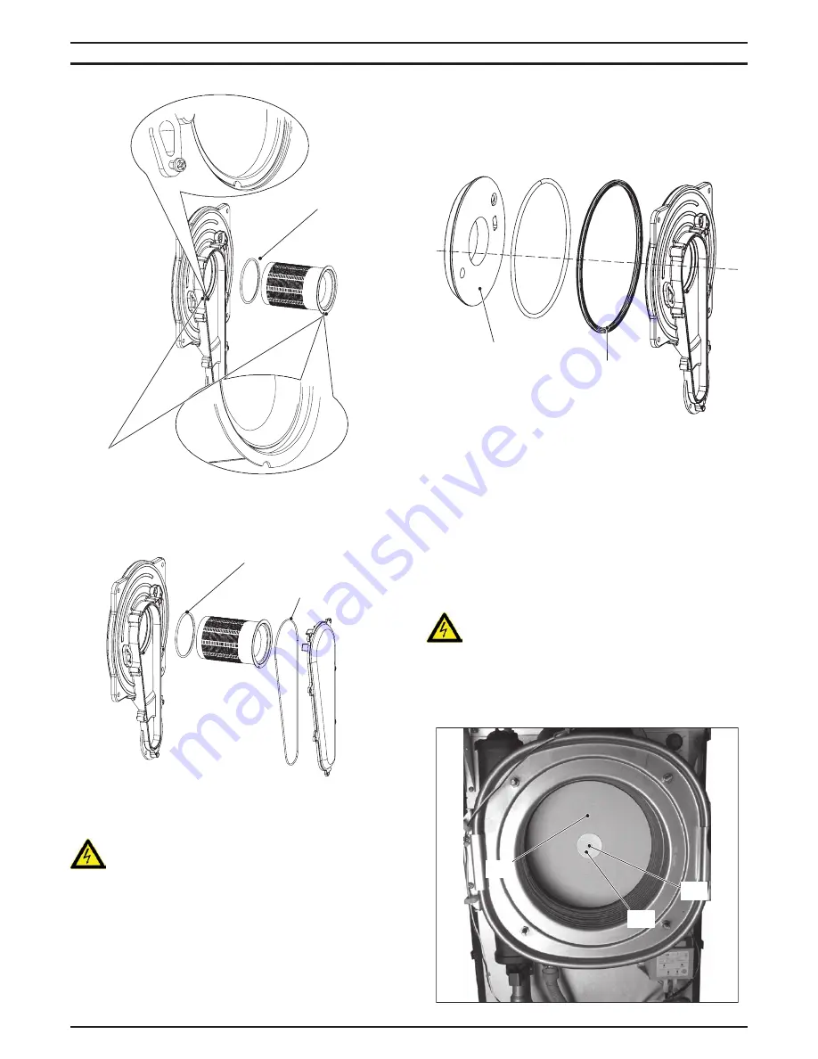
figure 18.4
locating tab
burner gasket
6 Assemble the burner carrying out the removal operation in re-
verse order. Ensure the burner is correctly located by lining up
the locating tab (Figure 18.4).
figure 18.5
burner gasket
Air---gas duct gasket
Before reassembling ensure the burner gasket is correctly lo-
cated.
Warning: After cleaning or replacement as detailed
above, it is deemed necessary to undertake a combus-
tion analysis as detailed in section "Adjustment" page
25.
18.4 Removal of the front insulation panel
See warning note at the end of this chapter before to remove
this part.
1 Remove the Ignition and detection electrodes (see section "Re-
moval of the Ignition and detection electrodes" page 36).
2 Remove the burner (see section "Removal of the burner" page
36).
3 Remove the front insulation panel (Figure 18.6).
4 Assemble the new front insulation carrying out the removal op-
eration in reverse order. When fitting the new panel ensure that
the electrodes holes coincide with the holes of the combustion
chamber.
figure 18.6
front insulation
Siliconic gasket
Caution:
After any periodical servicing or disturbance the combustion cham-
ber silicon seal (Figure 18.6) must be fully inspected and replaced at
the discretion of the service engineer.
After any disturbance to the chamber door seal the appliance must
undergo a full analytical combustion performance check.
18.5 Removal of the rear insulation
See warning note at the end of this chapter before to remove
this part.
Attention: Cover the inner of the condensing heat ex-
changer to avoid that dirt and debris fall in the coil.
1 Do the operations of section "Removal of the burner" page 36
from step 1 to step 3.
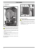
2 Unscrew the screw L, remove the washer M and the rear insula-
tion N (Figure 18.7).
figure 18.7
L
M
N


