- 61 -
INST
ALLA
TION
COMMISSIONING
periencing a harmonic noise from the boil-
er. In these circumstances, it may be nec-
essary to reset the burner gas pressures
in accordance with section 11 Gas Valve of
the Service Manual.
It should be noted that a Flue Gas Analyser
is required for this procedure.
7.8 Checking the inlet pressure
•
Remove the boiler front panel, see section
"Dismantling the external panels" on page
77.
•
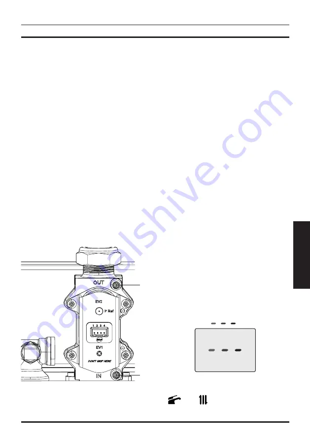
With the boiler switched on at full rate (maxi
-
mum output power), check the supply pres
-
sure by using the 27 point in Fig. 7.8 and
compare the value with that reported on
the Gas supply pressure table (minimum
inlet pressure) in the "Technical Data" sec
-
tion (page 28
M300V.2025 SM
, (page
32
M300V.2530 SM
and (page 36
M300V.3035 SM
).
•
Ensure the test nipple 27 in Fig. 7.8 is firmly
closed.
Fig. 7.8
29
27
If it does not comply with the required pres
-
sure check the gas supply line and governor
for faults and/or correct adjustment.
Where the boiler is connected to a gas sup-
ply which has a zero set governor then it is
necessary under the Gas Safe (Installation
and Use) Regulations 26.9. to perform a
combustion analysis test for CO/CO
2
(The
limits for the boiler is given in "Technical
Data" section (page 28 M300V.2025 SM,
(page 32 M300V.2530 SM and (page 36
M300V.3035 SM: CO
2
contents / other flue
gas figures) and complete the Certificate
of Exemption section of the Benchmark.
Important: after the checks all of the test
points must be sealed and tested for tight-
ness.
7.9 Lighting the boiler
Some products incorporate an anti cycling
time delay. It is normal when first switching
the boiler on for the boiler to operate on heat
-
ing for a few seconds then switch off. After
3-4 minutes has elapsed the boiler will then
re ignite and operate perfectly normally. The
ignition delay cycle does not prevent normal
operation of the boiler to provide D.H.W.
If external controls are fitted (e.g. Timeclock,
room thermostat) ensure they ”call for heat”.
•
Electrically power the boiler by switching on
the double pole isolation switch. The LCD
will display, the
symbol (Fig. 7.9).
Fig. 7.9
•
Press the 14 key for 5 seconds until both
and
symbols appear on the dis
-
play Fig. 7.10.


