background image

General requirements

rev 17 09 93

21

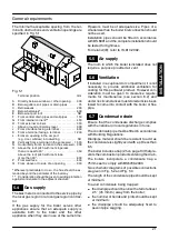
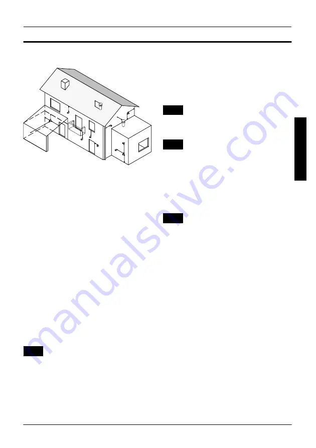
The minimum acceptable spacing from the ter-

minal to obstructions and ventilation openings are

specified in Fig. 5.1.

A

BC

E

F

G

I

JK

L

M

N

H

I

O

P

Q

D

Fig. 5.1

Terminal position

mm

A

Directly below a window or other opening

300

.

. . .

B

Below gutters, soil pipes or drain pipes

75

.

. . . . .

C

Below eaves

200

.

. . . . . . . . . . . . . . . . . . . . . . . . . . . .

D

Below balconies*

600

.

. . . . . . . . . . . . . . . . . . . . . . . .

E

Below car port roof

NO

.

. . . . . . . . . . . . . . . . . . . . . . .

F

From vertical drain pipes and soil pipes

150

.

. . . .

G

From internal corners**

450

.

. . . . . . . . . . . . . . . . . .

H

From external corners

300

.

. . . . . . . . . . . . . . . . . . .

I

Above ground or balcony level

300

. .

. . . . . . . . . . . .

J

From a surface facing a terminal

600

.

. . . . . . . . . . .

K

From a terminal facing a terminal

1 200

.

. . . . . . . . .

L

From an opening in the car port

.

(e.g. door, window) into dwelling

NO

. . . . . . . . . . .

M Vertically from a terminal in the same wall

1 500

.

N

Horizontally from a terminal in the same wall 300

.

.

O

Above the roof pitch with roof slope less

.

than or equal to 30

˚

350

. . . . . . . . . . . . . . . . . . . . . .

Above the roof pitch with roof slope

more than 30

˚

600

. . . . . . . . . . . . . . . . . . . . . . . . . . .

P

From wall face

600

.

. . . . . . . . . . . . . . . . . . . . . . . . . .

Q

From, above or to side of an opening

300

.

. . . . . . .

*Wherever practicable to do so, the flue should be ex-

tended beyond the perimeter of the balcony

** Consideration should be given to adding protection

against condensate to the adjacent structure

5.4

Gas supply

The Gas meter is connected to the service pipe by

the local gas region or a local gas region contrac-

tor.
If the gas supply for the boiler serves other

appliances ensure that an adequate supply is

available both to the boiler and the other

appliance when they are in use at the same time.

Pipework must be of adequate size. Pipes of a

smaller size than the boiler inlet connection should

not be used.
Installation pipes should be fitted in accordance

with BS 6891 and the complete installation should

be tested for tightness.
For Ireland (IE), refer to I.S.813.2002.

5.5

Air supply

The room in which the boiler is installed does not

require a purpose provided air vent.

5.6

Ventilation

If installed in a cupboard or compartment, it is not

necessary to provide additional ventilation for

cooling for this particular product. However con-

sideration must be given to clearance require-

ments for maintenance (see section 6.2) and

under no circumstances must stored articles be al-

lowed to come into contact with the boiler or flue

pipe.

5.7

Condensate drain

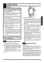
Ensure that the condensate discharge complies

with the national or local regulations in force.
The condensate pipe must be fitted in accordance

with Building Regulations.
Drainpipe material should be resistant to acid as

the condensate is slightly acid with a pH less than

6.5.
The boiler includes a trap (25 on page 13) that pre-

vents the combustion products entering the drain.
The boilers incorporate a condensate trap a

75mm seal ti comply with BS6798.2000.
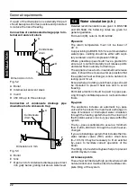
Two schematic diagrams of possible connections

are given in Fig. 5.2 and Fig. 5.3.
The length of the condensate pipe should be kept

at minimum.
To avoid condensate being trapped:

---

the drainpipe should be run with a fall of at least

2.5

˚

(45 mm/m) away from the boiler;

---

the number of bends and joints should be kept

at minimum;

---

the drainpipe should be adequately fixed to

pevent pipe sagging.

IN

S

TA

LLA

TI

O

N

Summary of Contents for M96A.24SM/B

Page 1: ...Wall hung fan flue room sealed high efficiency gas boiler User manual and Installation instructions GARDA HE MK2 Models M96A 24SM B Combi boiler M96A 28SM B Combi boiler...

Page 2: ...tight is of the correct gauge for the flow to the boiler is fitted with all the safety and control de vices required by the current Regulations n Ensure that the installer has connected the pressure r...

Page 3: ...ich can cause severe irritation to people wearing contact lenses Irritation to respiratory tract Precautions Dust goggles will protect eyes People with a history of skin complaints may be particularly...

Page 4: ...It is also sensible to initially fire and com mission the boiler before connecting any ex ternal controls such as a room thermostat By this method if you have a subsequent prob lem following the addi...

Page 5: ...25 6 3 Installing the bracket 25 6 4 Overall dimensions 26 6 5 Joints 26 6 6 Mounting the boiler 26 6 7 Fitting the flue system 27 6 8 Choice of flue 27 6 9 Electrical connections 30 6 10 External fr...

Page 6: ...reset button 8 Function selector and c h temp control knob 9 D h w temperature control knob 10 Appliance operation lights 1 3 Isolation valves 14 12 16 13 15 11 Fig 1 2 bottom view of the boiler 11 C...

Page 7: ...he above table a fault may be indicated Reference should be made to the following table In this case switch off the boiler as described in section 2 6 on page 6 and call a competent and re sponsible S...

Page 8: ...ro cedure you are advised to contact your In staller or an Approved Engineer This appliance is provided with a built in anti freeze system that operates the boiler when the temperature is below 5 C Th...

Page 9: ...le from a minimum of about 40 C to a maximum of about 85 C Fig 2 6 by turning the function se lector 8 Adjustment of c h output on the boiler is auto matic The greatest output pre set in the factory c...

Page 10: ...d water In this way the automatic control facilities will be fully exploited Moreover where the amount of limescale present in the water may be particularly great not exceed ing the position in Fig 2...

Page 11: ...position the time display G is flashing Set the mode selector switch A to the position and press the buttons D or E until the current time appears in the display G The clock starts by moving the swit...

Page 12: ...different position Manual operation The operation of the time switch can be forced on or off constantly or for a timed period To force constantly on or off the timer operation set the mode selector sw...

Page 13: ...rresponding to 14 on off sequences Press repeatedly the button A until the display shows the symbol C1 Fig 2 21 The symbols shown in Fig 2 21 appears in the display A Fig 2 21 Press the buttons D or E...

Page 14: ...A Fig 2 24 The operation can be switched permanently on or off by pressing the button F and leaving the dis play shows the symbol TIMER To force a timed delay on or off operation press repeatedly the...

Page 15: ...it is advisable to arrange maintenance and cleaning by an Authorised Service Centre En gineer at least once a year During the service the most important compo nents of the boiler will be inspected an...

Page 16: ...er comes out of the pressure relief valve Check on the temperature and pressure gauge 4 on page 2 that the pressure in the central heating circuit is not close to 3 bars In this case tempera ture rise...

Page 17: ...lve 25 Condensate trap 26 Automatic air purger valve 27 Pump vent plug 28 Pump 29 C h pressure relief valve 30 D h w flow switch 31 Modulation gas valve 32 Modulation operator 33 Gas valve outlet pres...

Page 18: ...Technical information 14 4 2 Main diagram 46 19 50 49 38 43 41 33 28 29 30 31 34 26 36 37 45 47 12 13 16 14 44 17 39 23 35 15 32 22 40 24 48 21 25 11 20 Fig 4 2 INSTALLATION...

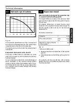
Page 19: ...or sys tem component cocks the by pass valve ensur es a minimum flow of water through the primary heat exchanger 4 4 Expansion vessel Note this boiler is designed for operation only in a sealed centr...

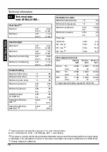
Page 20: ...r Maximum temperature C 55 Minimum temperature C 35 Maximum pressure kPa bar 1 000 10 Minimum pressure kPa bar 30 0 3 Flow rate minimum l min 2 5 30 rise C l min 11 6 35 rise C l min 10 0 40 rise C l...

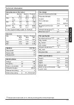
Page 21: ...mption W 140 Protection degree IPX4D External fuse rating A 3 Internal fuse rating A F1 F2 3 15 AF Flue design Type C12 C32 C42 C52 C82 Flue pipe diameter Coaxial mm 60 100 Twin split pipes mm 80 Roof...

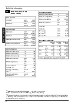
Page 22: ...r Maximum temperature C 55 Minimum temperature C 35 Maximum pressure kPa bar 1 000 10 Minimum pressure kPa bar 30 0 3 Flow rate minimum l min 2 5 30 rise C l min 13 6 35 rise C l min 11 6 40 rise C l...

Page 23: ...mption W 150 Protection degree IPX4D External fuse rating A 3 Internal fuse rating A F1 F2 3 15 AF Flue design Type C12 C32 C42 C52 C82 Flue pipe diameter Coaxial mm 60 100 Twin split pipes mm 80 Roof...

Page 24: ...is drawn tothe requirementsof the current I E E Wir ing Regulations and in Scotland the electrical provisions of the Building Regulations applicable in Scotland with respect to the installation of the...

Page 25: ...in use at the same time Pipework must be of adequate size Pipes of a smaller size than the boiler inlet connection should not be used Installation pipes should be fitted in accordance with BS 6891 and...

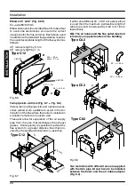
Page 26: ...ally to air release points and water flows naturally to drain taps The appliance has a built in automatic air release valve it should be ensured as far as possible that the appliance heat exchanger is...

Page 27: ...The installer should ensure that no leaks exist either inside the boiler or on the system as fre quent filling of the system could cause premature scaling of the heat exchanger 5 9 Domestic water The...

Page 28: ...overvoltage cat egory III Alternatively it can be used a 3A fused three pin plug and unswitched shuttered socket outlet both complying with BS 1363 The point of connection to the electricity supply m...

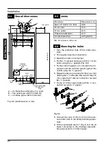
Page 29: ...with during installation To allow maintenance procedures it is necess ary to leave the minimum gaps indicated in Fig 6 1 25 50 250 200 Fig 6 1 all dimensions in mm When installing the boiler in a cup...

Page 30: ...boiler 1 Take the protective caps off the boiler pipe work 2 Thoroughly clean the connections 3 Mount the boiler on its bracket 4 Fix the c h valves A and gas cock B to the boiler using the gaskets F...

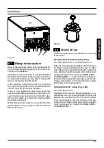
Page 31: ...with the boiler is fitted to the boiler Fig 6 5 6 8 Choice of flue The following flue kits are available for connecting to the boiler Standard horizontal flue kit Fig 6 6A Co axial 60 100mm nominal l...

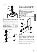
Page 32: ...here the boiler is installed in a location remote to an outside wall These kits allow for separation of the air supply pipe from the pipe that discharges the exhaust gasses Consequently it is possible...

Page 33: ...ll maximum permissible length Optional 45 and 90 elbowscan be used tooffset the flue route Each additional elbow reduces the overall accept able length of the flue system as follows 45 reduce length b...

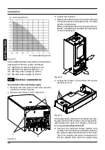
Page 34: ...J K I Fig 6 13 3 Loosen the screws K 4 Remove the side panels or move the lower part of the side panels as indicated in Fig 6 14 and pull the control panel When completely pulled out the panel can ro...

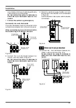
Page 35: ...1 and 3 as shown in Fig 6 17 Do not connect live wires to terminals to which the room thermostat must be con nected Power supply terminal block External controls terminal block T Room thermostat 1 2...

Page 36: ...de scribed in BS 6891 For Ireland IE refer to I S 813 2002 2 Open the gas cock 14 Fig 7 1 on the appliance and check the gas connector on the appliance for leaks Open position 14 13 Fig 7 1 7 3 Fillin...

Page 37: ...fter 3 4 minutes has elapsed the boiler will then re ignite and operate perfectly normally The ignition delay cycle does not prevent normal operation of the boiler to pro vide d h w If externalcontrol...

Page 38: ...A fullexplanation of the gas pressure adjustment procedure is given in the Gas Valve section of the service manual If maximum and or minimum gas pressures are adjusted then the ignition gas pressure...

Page 39: ...gures 7 11 Checking the condensate drain pipe Check the soundness and integrity of the conden sate drain pipe Verify the cleanness and correct filling of the con densate traps 7 12 Instructing the use...

Page 40: ...r 40 on page 13 See section Ignition and detection electrodesin the service manualfor detailed in structions 5 Carry out the conversion for the type of gas re placing the burner injectors correctly 6...

Page 41: ...neously 15 Open the gas cock 14 in Fig 8 7 Open position 14 Fig 8 7 16 To reset the boiler to the normal operation turn it ON by the function selector 8 on the desired operation and checking the ignit...

Page 42: ...or cleaning mainten ance opening or dismantling boiler panels 9 2 Dismantling the external panels Front panel 1 Loosen the three screws A Fig 9 1 2 Lift and remove the panel A Sampling points Air Flue...

Page 43: ...Cleaning the burner The sloping and multi gas type burner 40 on page 13 does not need special maintenance but it is sufficient to dust it with a bristle paintbrush To reach the burner 1 Take off the...

Page 44: ......

Page 45: ......

Page 46: ......

Page 47: ......

Page 48: ...1578 0 4908 48A5 UK Biasi UK Ltd Newman Park Western Way Wednesbury WS10 7BJ Sales Tel No 0121 506 1340 Sales Fax No 0121 506 1360 Service Tel No 0121 506 1350 Service Fax No 0121 506 1370 www biasi c...

Reviews: