background image


Installation 


29 

5.7 Electrical 

connections 


5.7 

Электрические


подсоединения


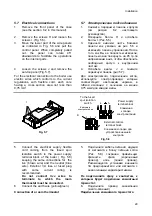
1.  Remove the front panel of the case 

(see the section  8.2 in this manual). 


1. 

Снимите


переднюю


панель


корпуса


(

см


раздел

 8.2 

настоящего


руководства

). 

2. 

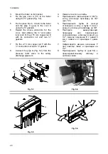
Remove the screws H and loosen the 
screws I .(Fig. 5.5). 


2. 

Отверните


болты


Н


и


ослабьте


болты

 I. (

Рис

.5.5) 

3. 

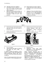
Move the lower part of the side panels 
as indicated in Fig. 5.6 and pull the 
control panel. When completely pulled 
out, the panel can rotate 45° 
downwards to facilitate the operations 
on the internal parts. 


3. 

Сдвиньте


нижнюю


часть


боковой


панели


как


указано


на


рис

. 5.6 

и


извлеките


панель


управления

После


того

как


Вы


ее


полностью


извлекли

панель


можно


повернуть


на

 45 

гр

.

по


направлению


вниз

чтобы


обеспечить


свободный


доступ


к


внутренним


частям

4. 

Loosen the screws J and remove the 
service panel (Fig. 5.7). 


4. 

Ослабьте


винты

 J 

и


снимите


сервисную


панель

 (

рис

.5.7).   

For the electrical connection to the boiler use 
electric wires which conform to the current 
regulations, with flexible cord, each core 
having a cross section area not less than 
0,75 mm

2


Для


электрического


подключения


котла

используйте


электропровода


которые


соответствуют


настоящим


нормам

в


гибкой


изоляции

с


сечением


не


менее


0,75 

мм

для


каждой


жилы


J


Fig. 5.7 


1

2

L

N


3

К


автомату


электропитания


Клеммная


колодка


электропитания


Клеммная


колодка


для


устройства


внешнего


контроля


Power supply 

terminal block

External controls 

terminal block 

To the fused 

spur isolation 

switch 


Fig. 5.8 


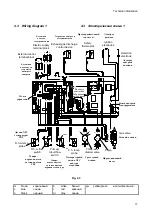
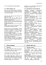
5.  Connect the electrical supply flexible 

cord coming from the fused spur 
isolation switch to the power supply 
terminal block of the boiler ( Fig. 5.8) 
keeping the same connections for  the 
live (brown wire) and the neutral (blue 
wire). External 3 A fuse or fused plug 
with same current rating is 
recommended. 


5. 

Подключите


кабель


питания

идущий


от


автомата


к


блоку


питания


котла


(

Рис

. 5.8) 

сохраняя


правильную


фазность

фаза


(

коричневый


провод

), 

ноль


(

синий


провод

). 

Рекомендуется


установка


внешнего


3

А


предохранителя


или


автомата


с


аналогичными


характеристиками

Do not connect live wires to 
terminals to which the room 
thermostat must be connected. 


Не


подключайте


фазу


к


контактам

к


которым


будет


подключен


комнатный


термостат

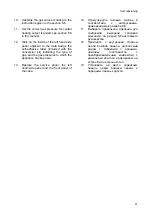
6. 

Connect the earth wire (yellow/green). 


6. 

Подключите


провод


заземления


(

желто

-

зеленый

Connection of a room thermostat 


Подключение


комнатного


термостата


Summary of Contents for NOVA PARVA M90.24A

Page 1: ...NOVA PARVA MODELS M90 24A M90 28A USER MANUAL AND INSTALLATION INSTRUCTIONS...

Page 2: ...tially the air intakes used to aerate the room where the boiler is installed to use extractor fans fire places and the like in the same room at the same time as the boiler to install a fan on the boil...

Page 3: ...of a qualified person Do not touch the appliance with parts of the body that are wet or damp and or bare feet In case of structural work or maintenance near the exhaust duct and or fume exhaust devic...

Page 4: ...ested live at the factory a small amount of water remains within the boiler It is possible for this water to initially cause the pump to seize It is therefore recommended that the pump rotor be manual...

Page 5: ...ry contact a competent service agent Appliance category II2H3 Gas G20 20 mbar G30 29 mbar G31 37 mbar II2H3 G20 20 G30 29 G31 37 This appliance conforms with the EEC directive 90 396 and consequently...

Page 6: ...stallation 31 6 2 Gas supply installation 31 6 3 Filling the d h w system 31 6 4 Initial filling of the system 31 6 5 Lighting the boiler 32 6 6 Checking the gas pressure at the burner 33 6 7 Adjustin...

Page 7: ...pressure gauge 4 5 Lock out signal lamp 5 6 Boiler reset button 6 7 Function switch and c h temperature adjustment knob 7 8 D h w temperature adjustment knob 8 9 Appliance operation light 9 1 3 Isola...

Page 8: ...Appliance description 2 10 12 13 14 15 16 11 Fig 1 2 bottom view of the boiler 1 2 1 4 Techincal data 1 4 For detailed technical data see section 4 5 or 4 6 of this manual 4 5 4 6 9 8 7 6 5 4 Fig 1 3...

Page 9: ...very 2 seconds normally operating boiler Function selector in or position 1 2 C h operation D h w operation Frost protect operation D h w operation Excessive temperature on primary circuit Faulty c h...

Page 10: ...2 2 4 2 2 If the pressure reading on the pressure gauge is below that shown in Fig 2 2 then the system will require topping up A filling loop is normally provided by the installer for this purpose 2 2...

Page 11: ...e any difficulty with the operation of the boiler switch off the boiler immediately at the fused spur isolation switch and contact your Installer or an approved Service Engineer The pressure should be...

Page 12: ...r isolation switch The appliance operation light 9 Fig 1 3 will flash every 4 seconds stand by condition 2 9 1 3 4 3 If the boiler is to be used for c h and d h w position the function selector 7 as i...

Page 13: ...aximum output in d h w operation Such adjustments must be carried out by a qualified person therefore we advise you to contact your installer or Service Agent Adjustment of the boiler temperature alte...

Page 14: ...ied from a minimum of about 35 C to a maximum of about 55 C Fig 2 8 by turning the knob 8 35 55 2 8 8 8 Minimum 8 Maximum Fig 2 8 Adjustment of the d h w temperature is completely separate from that o...

Page 15: ...its and clogging 2 9 8 50 2 9 In these cases however it is advisable to install a small water treatment device or softener With such a device you should avoid periodic descaling Consequently the d h w...

Page 16: ...supply to the boiler by means of the fused spur isolation switch 1 2 Shut off the gas supply cock 14 and the cocks for the water circuits fitted under the boiler Fig 2 11 2 14 2 11 3 Empty the water...

Page 17: ...by means of the room thermostat and the knob 7 in Fig 3 1 7 3 1 7 Fig 3 1 3 2 Frost protection 3 2 The built in antifreeze system and any additional system protect the boiler from possible damages du...

Page 18: ...of the central heating circuit bleeding of air from the central heating system general check of the appliance s operation 3 4 External cleaning 3 4 Before doing out any cleaning disconnect the applia...

Page 19: ...uge 4 on section 1 2 has gone down 4 1 2 it is necessary to top up the appliance with water again so as to raise the pressure to an adequate level as described in the section 2 2 of this manual 2 2 If...

Page 20: ...appliance cleaned out by an Authorised Service Centre Engineer If water should occasionally leak from the boiler shut off the taps positioned under the boiler Fig 2 11 and call an Authorised Service...

Page 21: ...rter valve 28 Flame detecting electrode 29 Ignition electrodes 30 Burner 31 Combustion chamber 32 Primary heat exchange 33 Flue hood 34 Exaust gas discharge control device 35 Safety thermostat 36 Modu...

Page 22: ...Technical information 16 4 2 Main diagram 4 2 17 18 19 20 22 23 24 25 26 27 28 29 30 31 32 33 34 35 40 41 11 14 12 16 13 15 39 43 42 37 38 36 Fig 4 2...

Page 23: ...b n 1 3 2 n c m g v m m c m External control terminal block Electric supply terminal block Safety thermostat Ignition electrodes Detection electrode D h w temp probe D h w flow switch Primary circuit...

Page 24: ...b n 1 3 2 n c m g v m m c m External control terminal block Electric supply terminal block Safety thermostat Ignition electrodes Detection electrode D h w temp probe D h w flow switch Primary circuit...

Page 25: ...5 C and 1013 25 mbar 15 1013 25 G20 34 02 MJ m3 G30 45 65 MJ kg G31 46 34 MJ kg 1 mbar aprox equals 10 mm H2O 1 10 2 Domestic hot water Maximum temperature C 55 Minimum temperature C 35 kPa 1000 Maxim...

Page 26: ...0 Power consumption W 95 Protection degree IPX4D Flue gas figures Nominal heat input kW 26 6 CO2 Content 2 5 1 O2 Content 2 11 8 CO Content ppm 100 Exhaust temperature C 115 Flue design Boiler type B1...

Page 27: ...c value at 15 C and 1013 25 mbar 15 1013 25 G20 34 02 MJ m3 G30 45 65 MJ kg G31 46 34 MJ kg 1 mbar aprox equals 10 mm H2O 1 10 2 Domestic hot water Maximum temperature C 55 Minimum temperature C 35 kP...

Page 28: ...umption W 95 Protection degree IPX4D Flue gas figures Nominal heat input kW 31 1 CO2 Content 2 6 3 O2 Content 2 9 7 CO Content ppm 100 Exhaust temperature C 130 Flue design Boiler type B11BS 11 S Nomi...

Page 29: ...the primary heat exchanger 41 4 1 In case of excessive reduction or total blockage of water circulation in the central heating system owing to closure of the thermostatic valves or system component co...

Page 30: ...volume of water in the system l 132 Tab 4 1 Where conditions are Average maximum temperature of the system is 80 C 80 Initial temperature when filling up the system is 10 C 10 For systems with volumes...

Page 31: ...to a suitable drain or discharge in a safe manner The electrical wiring must conform with current Regulations in particular the boiler must be earthed using the correct bonding clamp a fused spur iso...

Page 32: ...its It is advisable to equip the system with a sediment filter or use a water treatment product in the circulating water The latter option in particular not only cleans out the system but also has an...

Page 33: ...ket 20 O 105 115 115 601 100 60 Gas D c w C h r C h f O 18 Flue pipe axis O Flue pipe axis 24kW O Boiler axis O a Flue pipe axis 28kW O Fig 5 2 5 5 Joints 5 5 Functions Pipe sizes Gas c h return c h f...

Page 34: ...gaskets 5 3 4 6 Repeat the above procedure for the d c w inlet utilising the cold water inlet cock D the 15 mm copper tail E with its connection nut and two gaskets 6 D 1 2 15 2 1 2 7 Fix the 15 mm co...

Page 35: ...wires which conform to the current regulations with flexible cord each core having a cross section area not less than 0 75 mm2 0 75 2 J Fig 5 7 1 2 L N 3 K Power supply terminal block External control...

Page 36: ...to terminals to which the room thermostat must be connected The insulating class of the room thermostat must be II or the thermostat must be correctly earthed 2 8 Route the electrical supply flexible...

Page 37: ...Gas supply installation 6 2 1 Inspect the entire installation including the gas meter test for soundness and purge 1 2 Open the gas cock 14 Fig 6 1 on the appliance and check the gas connector on the...

Page 38: ...plug 7 8 Continue filling the system The actual reading should ideally be 1 3 bar and not less than 0 3 bar 8 1 3 0 3 9 Close all air release valves on the c h system 9 10 Inspect the boiler and the...

Page 39: ...release the boiler reset button 6 Fig 6 3 6 6 3 6 6 Checking the gas pressure at the burner 6 6 This boiler has been tested to the highest quality control standards The maximum and minimum gas pressu...

Page 40: ...maximum gas pressure and compare the value on the gauge with the value indicated in the sections 4 5 4 6 gas pressures at the burner accordingly with the model of boiler installed 7 4 5 4 6 8 To adjus...

Page 41: ...sections 4 5 4 6 gas pressures at the burner accordingly with the model of boiler installed If the ignition gas pressure is not set correctly see section 6 7 in this manual for the adjustment procedu...

Page 42: ...test point 37 Fig 6 4 and connect a pressure gauge 3 37 6 4 4 Loosen the screws D and remove the service panel Fig 6 6 4 D 6 6 D Fig 6 6 2 3 4 OFF ON 1 ACC RISC Fig 6 7 5 Turn on the boile 5 6 Check t...

Page 43: ...or adjusting the c h output and fault finding on the boiler it may be necessary to switch the re ignition delay mechanism dipswitch 4 to the OFF position 4 OFF Refer to the diagrams shown in Fig 6 8...

Page 44: ...lock out signal lamp 5 Fig 1 3 must appear 10 5 1 3 To reset the boiler press and release the boiler reset button 6 Fig 1 3 6 1 3 6 10 Checking the flue system 6 10 The flue system should be visually...

Page 45: ...rt and long periods and advise on the precautions necessary to prevent damage should the appliance be inoperative when freezing conditions may occur Fill in the details required on the Boiler Guarante...

Page 46: ...1 4 30 4 1 5 Carry out the conversion for the type of gas replacing the burner injectors correctly 5 6 Re assemble the burner the front panel of the combustion chamber and the removable front of the...

Page 47: ...ut required see section 6 8 in this manual 11 6 8 12 Stick on the inside of the left hand side panel adjacent to the data badge the self adhesive label included with the conversion kit indicating the...

Page 48: ...a year maintenance and cleaning done by an Approved Service engineer Isolate the appliance from the electricity supply by turning off the fused spur isolation switch adjacent to the appliance and turn...

Page 49: ...ystem 8 4 1 Close the c h isolating valves 1 2 Open the central heating drain cock 18 in Fig 8 4 2 18 8 4 8 5 Cleaning the primary heat exchanger 8 5 Take off the front panel of the case then the seal...

Page 50: ...burner 8 2 The sloping and multi gas type burner 30 on section 4 1 does not need special maintenance but it is sufficient to dust it with a bristle paintbrush 30 4 1 8 3 Visual inspection of applianc...

Reviews: