background image

Useful advice 

12 


5

6


Fig. 3.2 


For the first lighting up and following 
maintenance procedures for the gas supply, it 
may be necessary to repeat the resetting 
operation several times so as to remove the 
air present in the pipework. 


При


первом


запуске


котла


и


последующих


процедурах


по


обслуживанию


газопровода

возможно


будет


необходимо


произвести


несколько


раз


перезапуск


котла

чтобы


удалить


воздух


из


трубопроводов

If noises due to air bubbles are heard 
during operation... 


Если


во


время


работы


котла


слышен


шум


воздушных


пузырьков

.. 

you should check that the pressure on the 
temperature and pressure gauge (Fig. 2.2) is 
not below the correct setting. 
If required, top up the system correctly, as 
described in the section 2.2 of this manual. 
Bleed any air present in the radiators, if 
necessary. 


проверьте

чтобы


показания


на


термоманометре

  (

рис

.2.2) 

были


не


ниже


выбранных


параметров

Если


необходимо

произведите


дозаполнение


системы

как


это


описано


в


разделе

 2.2 

настоящей


инструкции

.                                                

При


необходимости


спустите


воздух


из


радиаторов

If the pressure on the temperature and 
pressure gauge (4 on section 1) has gone 
down... 


Если


давление


на


термонамотре

 (4 

на


разделе

  1) 

начало


падать

..  

it is necessary to top up the appliance with 
water again, so as to raise the pressure to an 
adequate level as described in the section 2.2 
of this manual.. 


необходимо


дозаполнить


систему


водой

чтобы


давление


достигло


значения

описанного


в


разделе

 2.2 

настоящего


руководства

If topping up with water has to be done very 
frequent, have the system checked for leaks. 


Если


Вам


часто


приходится


дозаполнять


систему

проверьте


ее


на


наличие


утечек

If water comes out of the pressure relief 
valve 


Если


из


предохранительного


клапана


идет


вода


Check that the C.h. circuit filling valve is 
closed as described in the section 2.2 of this 
manual. 


Проверьте

чтобы


кран


заполнения


системы


отопления


был


закрыт

как


это


описано


в


разделе

 2.2 

настоящего


руководства

Check on the temperature and pressure 
gauge (4 on section 1) that the pressure in 
the central heating circuit is not close to 3 
bars. In this case, temperature rise in the 
circuit can cause the pressure relief valve to 
open. 


Проверьте


показания


давления


на


термоманометре

 (4 

на


разделе

 1)   

и


убедитесь


в


том

что


давление


в


контуре


отопления


не


превышает

 3 

бара

.  

В


противном


случае

при


возрастании


температуры


в


контуре

может


произойти


сработка


предохранительного


клапана

So that this does not happen and to decrease 
the pressure to a normal value, it is advisable 
to vent some of the water in the appliance 
through the bleed valves present in the 
radiators. 


Чтобы


этого


не


произошло


и


чтобы


понизить


давление


до


нормального


значения

рекомендуется


слить


некоторое


количество


воды


из


системы


через


сливные


краны


радиаторов


Installation 


29 

клеммная


коробка


температурного

датчика

 NTC 

накопительного

б й

D.h.w. storage tank temp.
probe NTC terminal block


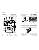
Fig. 5.14 

Terminals to
be connected
to the temp.
probe

To the storage
tank

K

леммы

,

которые
должны


быть

подключены


к

температурно
му


датчику

накопительному

бойлеру


Fig. 5.15 

STORAGE TANK
TEMP. PROBE

LONGEST
PROBE
SHEATH

температурный


датчик

K

ожух

датчика


Fig. 5.16 

1
2
3
4
5
6
7
8
9


Fig. 5.17 


5.10. Only C.h. boiler 


5.10 

Котел


для


отопления


The boiler is fitted to operate with a storage 
tank. 


Котел


предназначен


также


для


работы


с


накопительным


бойлером

If the boiler isn't connected to the storage 
tank

, fit the setting jumpers on the main 

control p.c.b. as indicaded in Fig. 5.17. 


Если


котел


не


подключен


к


накопительному


бойлеру

установите


переключатели


главного


блока


управления


в


положение

как


указано


на


рис

. 5.17 

To set the setting jumpers isolate the boiler 
from the mains electricity supply. 


Чтобы


установить


переключатели

отключите


котел


от


электросети

Summary of Contents for PARVA CONTROL M90.24AV

Page 1: ...1796211072 17962 1107 2 4606 52A5 PARVA CONTROL MODEL M90 24AV USER MANUAL AND INSTALLATION INSTRUCTIONS...

Page 2: ...erous to obstruct even partially the air intakes used to aerate the room where the boiler is installed to use extractor fans fire places and the like in the same room at the same time as the boiler to...

Page 3: ...the gas cocks get the assistance of a qualified person Do not touch the appliance with parts of the body that are wet or damp and or bare feet In case of structural work or maintenance near the exhaus...

Page 4: ...ng the addition of an external control you can eliminate the boiler from your fault analysis Do not forget to range rate the boiler to suit the system requirements This procedure is covered in the com...

Page 5: ...e boiler to follow the timed settings Some products incorporate an anti cycling time delay It is normal when first switching the boiler on for the boiler to operate on heating for a few seconds then s...

Page 6: ...1 Warnings 39 7 2 Procedures 39 8 Maintenance 8 1 Warnings 41 8 2 Dismanting the external panels 41 8 3 Emptying the ch system 42 8 4 Cleaning the primary heat exchanger 42 8 5 Checking the pressurisa...

Page 7: ...e left hand side panel adjacent to the data badge the self adhesive label included with the conversion kit indicating the type of gas and the gas pressures to which the appliance has been set 11 12 Re...

Page 8: ...tructions relating to the procedures for adapting the boiler to the type of gas available and subsequent calibration described below are presented in sections 6 5 and 6 6 6 5 6 6 7 2 Procedures 7 2 1...

Page 9: ...ur Fill in the details required on the Boiler Guarantee Certificate and hand to the User advising them to return the correct section for boiler Guarantee registration Finally advise the User that for...

Page 10: ...s normally provided by the installer for this purpose 2 2 If you are in any doubt regarding this procedure you are advised to contact your Installer or an Approved Engineer This appliance is provided...

Page 11: ...ment potentiometer marked RISC Fig 6 8 Rotating the potentiometer anti clockwise reduces the maximum supply current to the gas modulator device and thus reduces the gas pressure to the burner RISC 6 8...

Page 12: ...e operation light 9 will flash every 2 seconds operating boiler 4 7 2 5 9 2 Commissioning 35 6 6 Adjusting the burner ignition 6 6 1 Turn off the boiler by means of the fused spur isolation switch pro...

Page 13: ...ment will be necessary A full explanation of the gas pressure adjustment procedure is given in the Gas Valve section of the service manual If maximum and or minimum gas pressures are adjusted then the...

Page 14: ...iance operation light 9 will flash every 4 seconds 7 2 9 9 4 Commissioning 33 5 Set the d h w and c h temperature control knobs to their maximum position 5 6 Switch on the boiler and if external contr...

Page 15: ...panel of the case see section 8 2 in this manual 1 8 2 2 Open the gas valve inlet pressure test point 36 in Fig 6 5 at the valve input connect a suitable pressure gauge check the gas pressure of the s...

Page 16: ...ll turn and leave open permanently 3 21 6 2 1 4 Open the C h circuit filling valve 12 in Fig 6 1 and fill the C h circuit see section 2 2 4 12 6 1 2 2 5 Open each radiator air release tap starting wit...

Page 17: ...be inspected and cleaned This service can be part of a maintenance contract In particular you are advised to have the following checks carried out primary heat exchanger domestic hot water storage tan...

Page 18: ...ter comes out of the pressure relief valve Check that the C h circuit filling valve is closed as described in the section 2 2 of this manual 2 2 Check on the temperature and pressure gauge 4 on sectio...

Page 19: ...ting it upwards 5 14 Connect the two temperature probe wires between D h w storage tank temp probe terminals Fig 5 15 5 15 Insert D h w storage tank temp probe in the longest probe sheath Fig 5 16 5 1...

Page 20: ...on switch Fig 5 11 T 1 2 L N 3 Room thermostat Power supply terminal block External controls terminal block Fig 5 12 5 Connect the electrical supply flexible cord coming from the fused spur isolation...

Page 21: ...to facilitate the operations on the internal parts 3 5 9 45 4 Loosen the screws J and remove the service panel Fig 5 10 4 J 5 10 For the electrical connection to the boiler use electric wires which co...

Page 22: ...C h temp probe NTC Primary circuit flow switch Three way diverter valve D h w storage tank temp probe NTC NTC Pump Gas valve Installation 25 5 7 Installing the D h w storage tank 5 7 D h w storage tan...

Page 23: ...l information 17 4 4 Technical Data mod M90 24AV 4 4 Nominal heat input kW 26 6 Minimum heat input kW 11 0 Maximum useful output kW 24 0 Minimum useful output kW 9 3 Central heating Temp regulation ra...

Page 24: ...ney working at the nominal heat input 1 Installation 23 5 3 Installing the bracket 5 3 Precautions Utilise the paper template supplied with the boiler to determine the fixing position for the bracket...

Page 25: ...by promoting formation of a protective skin on metal surfaces and neutralising gases present in the water Technical information 19 4 5 Hydraulic specifications 4 5 0 00 0 10 0 20 0 30 0 40 0 50 0 2 0...

Page 26: ...d only in an adequately ventilated room in conformity with the standards A minimum air flow rate of 2 m3 h per kW of max heat input must be ensured 2m3 For LPG the appliance must also conform with the...

Reviews: