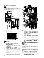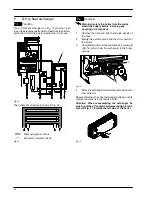
General access and emptying hydraulic circuits
3
Fig. 4
5
Remove the screws
E
and remove the service
panel (Fig. 5);
6
To gain access to the electronic regulation PCB
remove the screws
F
and remove the control pan-
el lid (Fig. 5);
E
F
F
Fig. 5
2.4
Access to the sealed chamber
G
G
Fig. 6
To gain access to the parts contained in the sealed
chamber it is necessary to remove the lid of the sealed
chamber.
For this purpose, remove the front and side panels of
the case, remove the screws
G
as indicated in Fig. 6
and remove the lid.
2.5
Emptying the primary circuit
1
Close the c.h. circuit flow and return cocks
H
.
(Fig. 7).
H
H
J
Fig. 7 --- bottom view of the boiler
2
Remove the front and right panels of the boiler.
3
Open the drain tap
I
(Fig. 8) until the boiler is com-
pletely emptied.
4
Close drain tap again once the emptying has
been completed.
I
Fig. 8
2.6
Emptying the d.h.w. circuit
5
Close the d.c.w. inlet cock
J
(Fig. 7);
6
Open one or more hot water taps until the boiler
has been completely emptied.


