- 28 -
INST
ALLA
TION
INSTALLATION
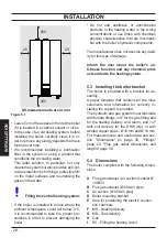
Figure 5.1
25
25
All measurements are in mm
250
200
• Leave 5 cm of free space in front of the boiler
if it is inserted in a cabinet, shelter or niche.
• In the case of an old heating system, before
installing the boiler, carefully clean it in or-
der to remove any sludgy deposits that have
formed over time.
•
We recommended installing a purification
filter in the system or using a product that
conditions the circulating water.
This latter solution, in particular, not only
cleans the system but also provides anti-cor-
rosion protection by forming a protective film
on the metal surfaces and neutralising the
gases in the water.
Filling the central heating system:
• If the boiler is installed in rooms where the
ambient temperature could fall below 0°C,
it is recommended to take the proper pre-
cautions in order to prevent damaging the
boiler.
• Do not add antifreeze or anticorrosion
products to the heating water in the wrong
concentrations or use those with chemical/
physical characteristics that are incompati-
ble with the boiler’s hydraulic components.
The manufacturer does not assume any liabil-
ity for this type of damage.
Inform the user about the boiler’s an-
ti-freeze function and any chemical prod-
ucts added to the heating system.
5.3 Installing the boiler bracket
The boiler is provided with a bracket for as-
sembly.
A paper template that contains all the mea-
surements and information for correctly in-
stalling the support is provided.
The hydraulic and gas system must terminate
with female fittings, 3/4" for the gas fitting and
for the heating delivery and return, and 1/2"
tank coil delivery for the DHW inlet, or with
welded copper pipes - Ø 18 mm and Ø 14 mm.
For measurements and useful data see sec-
tion "Dimensions" on page 28, "Fittings"
page 29, "Flue gas outlet dimensions and
lengths" page 30.
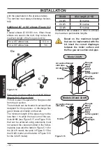
5.4 Dimensions
The boiler complies with the following dimen-
sions:
A
Flue gas exhaust / air suction (coaxial Ø
100/60)
B
Flue gas exhaust (Ø 80 twin pipe)
C
Air suction (Ø 80 twin pipe)
D
Boiler mounting bracket
E
Area for positioning the electric connec-
tion channels
F
MR - Heating delivery
G
MB - Tank delivery
H
Gas
I
RC - Filling the heating circuit
Summary of Contents for RINNOVA CV Series
Page 1: ...User manual and installation instructions RINNOVA CV...
Page 65: ...65 NOTE...
Page 66: ...66 NOTE...
Page 67: ......


