background image

- 4 -

W

ARNING

DURING USE

  It is prohibited and dangerous

 to obstruct, even partially, the air intakes for the ventila-

tion of the room where the boiler is installed (UNI 11071 and related standards);

 Repairs

 must only be carried out by authorised service centres using original spare parts. 

Therefore, in the case of a problem, deactivate the boiler only (see instructions).

  If you smell gas:

• Do not turn on electric switches, the telephone or any other object that could create 

sparks.

• Immediately open up the doors and windows to create an air current that cleans the 

room.

•  Close the gas cocks.

•  Request the intervention of professionally qualified personnel.

  Before starting the boiler

, have a qualified professional check that the gas supply sys

-

tem:

•  Is perfectly sealed.

•  Is the right size for the required flow rate to the boiler.

•  Is equipped with the safety and control devices required by current standards;

•  Make sure that the installer has connected the safety valve drain to a outlet funnel.

  The manufacturer is not responsible for damage caused by the water released when 

the safety valve opens, if it is not correctly connected to a drainage system.

•  Make sure that the installer has connected the condensate siphon drain to a specific 

outlet funnel (UNI 11071 and related standards), which must be implemented in order 

to avoid the condensate freezing and ensure it is correctly drained.

  Do not touch the unit

 with wet or damp body parts and/or in bare feet.

  If performing structural work or maintenance

 near the flue gas ducts and/or the flue 

gas exhaust devices or their accessories, turn off the unit and, when the work is complete, 

have a qualified technician check the efficiency.

Appliance category: 

II

2H3P (gas G20 20 mbar, G31 37 mbar)

Destination country: IT

This unit is compliant with the following European Directives:

Gas Appliance Directive 2009/142/EC

Boiler Efficiency Directive 92/42/EEC

Electromagnetic Compatibility Directive 2004/108/EC

Low Voltage Directive 2006/95/EC

In order to constantly improve its products, the manufacturer reserves the right to change the data pro-

vided in this documentation at any time and without notice.

This documentation is provided for information purposes and cannot be considered as a contract with 

third parties.

Summary of Contents for RINNOVA CV Series

Page 1: ...User manual and installation instructions RINNOVA CV...

Page 2: ...e g injuries or bruises DANGER Instructions marked with this symbol must be observed to avoid electrical accidents electrocution DANGER Instructions marked with this symbol must be observed to avoid t...

Page 3: ...your retailer or the nearest authorised service centre Installation must be carried out by qualified personnel who are responsible for compli ance with all applicable national and local laws and stand...

Page 4: ...age caused by the water released when the safety valve opens if it is not correctly connected to a drainage system Make sure that the installer has connected the condensate siphon drain to a specific...

Page 5: ...n of the remote control optional 40 5 15 Enabling of operation with remote control optional 40 5 16 Installing the external temperature sensor 41 5 17 Electrical connection between the boiler and the...

Page 6: ...let Install an isolation valve for the gas inlet The figures in this manual only show one of the possible ways of installing cocks pipes and fit tings Figure 1 2 2 3 4 5 7 9 10 8 6 2 Gas supply label...

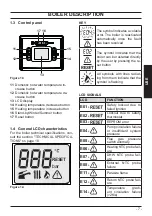
Page 7: ...cates a volatile error The boiler is reactivated automatically once the fault has been resolved The symbol indicates that the boiler can be restarted directly by the user by pressing the re set button...

Page 8: ...flash LCD FUNCTION E22 Heating delivery tem perature between 90 C and 100 C E25 Boiler in antifreeze E26 Gas valve fault E28 Tank NTC probe failure E50 Communication with remote control lost E52 Maxi...

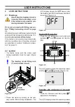
Page 9: ...2 2 Ignition The boiler cocks and the cocks used during installation must be open Figure 2 1 The heating circuit filling cock 7 must remain closed Figure 2 1 Open position 7 Power the boiler by turni...

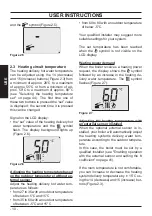
Page 10: ...between 5 C and 15 C from 35 to 60 with an outdoor temperature of between 5 C and 5 C from 60 to 80 with an outdoor temperature of below 5 C Your qualified installer may suggest more suitable setting...

Page 11: ...egionella in the domestic hot water the anti legionella function can be activated see Anti legio nella function on page 39 This function raises the temperature of the water contained in the hot water...

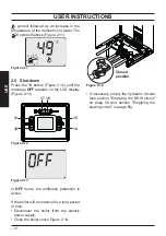
Page 12: ...CD display Figure 2 13 Figure 2 12 11 12 14 15 16 17 Figure 2 13 bar RESET In OFF mode the antifreeze protection is active If the boiler will be inactive for a long period of time Disconnect the boile...

Page 13: ...m thermostat is installed If a radiator or convector does not heat up check if there is any air in the system and make sure that the cock is open If the room temperature is too high do not adjust the...

Page 14: ...an error code flashes on the display and the symbol is shown it is a volatile lockout The boiler is reactivated automatically once the fault has been resolved see General LCD char acteristics on page...

Page 15: ...and call a techni cian from the authorised service centre 3 7 Displays in INFO mode INFO mode is used to view boiler status in formation In the case of a boiler malfunc tion provide this information t...

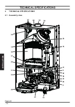
Page 16: ...16 INSTALLATION TECHNICAL SPECIFICATIONS 4 TECHNICAL SPECIFICATIONS 4 1 Assembly view Figure 4 1 19 34 37 20 29 36 32 31 25 10 22 6 21 23 30 24 8 18 33 40 41 39 38...

Page 17: ...e 7 Heating circuit filling cock 8 Heating circuit drain cock 9 Tank coil and heating return pipe 10 Heating circuit pressure gauge 18 Heating NTC Max temperature NTC 19 Primary exchanger 20 Flame det...

Page 18: ...ambient thermo stat cable or remote control optional thermostat or hot water tank sensor electric power supply cable 30 Heating pressure switch 31 Three way valve 32 Three way valve plug 33 Fan 34 Flu...

Page 19: ...M COM 1 NO 3 b b b c c n n c r b r c 2 5 7 8 9 10 11 12 1 3 4 6 a orange b white c blue g yellow gr grey m brown n black r red v purple g v yellow green 1 Electrical power supply 4 Pump 7 Boiler ther...

Page 20: ...oss at the chimney with burner operating Pf 6 3 Heat loss at the chimney with burner off T 50 C Pfbs 0 2 Heat loss towards the environment through the casing with the burner operating Pd 0 9 NOx class...

Page 21: ...1 Pa 2520 mbar 25 2 Nozzles N mm 100 Methane G20 11 130 Propane G31 11 78 Chimney design Max flue gas temperature C 123 Min flue gas temperature C 110 Max flue gas mass flow rate kg s 0 0154 Min flue...

Page 22: ...t loss at the chimney with burner operating Pf 5 2 Heat loss at the chimney with burner off T 50 C Pfbs 0 2 Heat loss towards the environment through the casing with the burner operating Pd 1 5 NOx cl...

Page 23: ...1 Pa 2490 mbar 24 9 Nozzles N mm 100 Methane G20 14 130 Propane G31 14 77 Chimney design Max flue gas temperature C 111 Min flue gas temperature C 100 Max flue gas mass flow rate kg s 0 0171 Min flue...

Page 24: ...t loss at the chimney with burner operating Pf 5 9 Heat loss at the chimney with burner off T 50 C Pfbs 0 2 Heat loss towards the environment through the casing with the burner operating Pd 1 NOx clas...

Page 25: ...1 Pa 2320 mbar 23 2 Nozzles N mm 100 Methane G20 15 130 Propane G31 15 78 Chimney design Max flue gas temperature C 125 Min flue gas temperature C 114 Max flue gas mass flow rate kg s 0 0196 Min flue...

Page 26: ...closure of thermostatic valves or circuit cocks the by pass guarantees a min imum circulation of water inside the primary condensate exchanger The by pass is calibrated for a differential pressure of...

Page 27: ...ts pro vided by the manufacturer as they are an in tegral part of the boiler For LPG gas Propane G31 the installation must also comply with the requirements of the distributing companies and with the...

Page 28: ...th chemical physical characteristics that are incompati ble with the boiler s hydraulic components The manufacturer does not assume any liabil ity for this type of damage Inform the user about the boi...

Page 29: ...fill heating circuit fitting and put the gasket with filter in place B Figure 5 3 Screw the cock on the boiler Figure 5 3 B A Tighten the quick fittings and taps on the hy draulic system Figure 5 4 In...

Page 30: ...ng indi cated in Figure 5 7 Figure 5 7 4 Connect the hot water tank coil return RR to the heating return pipe 9 in Figure 5 8 Figure 5 8 9 5 8 Flue gas outlet dimensions and lengths The flue gas outle...

Page 31: ...e of the boiler The minimum length of the duct and the max imum length with an extension must comply with the following parameters Figure 5 10 Coaxials 60 100 mm Diaphragm M290E 24CV For lengths betwe...

Page 32: ...max sum of the sec tions A B see Figure 5 17 and Figure 5 18 that can be achieved using extensions must not exceed the values provided in the follow ing table see also the table in Figure 5 14 for th...

Page 33: ...gure 5 16 M290E 32CV Twin split pipes 80 80 mm Diaphragm Flue gas Air For lengths between 0 5 m and 3 5 m 50 mm no For lengths between 3 5 m and 15 m no no Figure 5 17 C12 If the flue gas outlet pipe...

Page 34: ...flue gases directly through the roof Figure 5 19 L max 90 45 125 C32 Extensions are available for reaching the maximum height Its maximum height L Figure 5 19 with the extensions is Figure 5 20 Coaxia...

Page 35: ...21 B22 Extensions are available in order to achieve the maximum permissible lengths Figure 5 22 B22 80 mm outlet Diaphragm M290E 24CV For lengths between 0 5 m and 15 m 38 mm M290E 28CV For lengths b...

Page 36: ...he screw O and lift the cover P to release the cables from the cable gland Figure 5 24 Loosen the screws Q and lift the cover R Figure 5 24 Figure 5 24 N O P Q R Connecting to the electric power suppl...

Page 37: ...rolled by the room thermostat Figure 5 27 L N V T Zone valve with micro contacts Combustion chamber ambient Volt free contacts for the zone micro valves Use the room thermostat cable indicated in Figu...

Page 38: ...nd setting To connect the hot water tank thermostat to the boiler use electric cables with a section no less than 0 50 mm2 The electrical conductors for connecting the probes to the boiler must go thr...

Page 39: ...Accessing the pro gramming mode on page 37 By using buttons 14 or 15 Figure 5 28 it is possible to modify the value of parameter A18 00 NTC probe tank with probe 01 Thermostat ON OFF tank heating only...

Page 40: ...11 or 12 to confirm the value entered and return to the list of parameters Press button 16 to exit programming mode This function is activated 6 hours after be ing set 5 14 Electrical connection of t...

Page 41: ...s they are supplied at a safe low voltage and cannot exceed 20 metres in length Use the control board terminals indicated in Figure 5 41 to connect the external sensor The external sensor connection w...

Page 42: ...for setting the K coefficient Enter programming mode by holding down buttons 16 and 17 for 5 seconds at the same time Figure 5 44 The code P00 appears on the display indicating entry into parame ter P...

Page 43: ...ll follow the trend in relation to the set K co efficient If the room temperature is not comfortable you can increase or decrease the heating system delivery temperature by 5 C using the 14 decrease a...

Page 44: ...C low temperature Press 11 or 12 Figure 5 51 to confirm the value entered and return to the list of param eters Figure 5 53 Press the 16 button Figure 5 51 to exit programming mode 5 20 Selecting the...

Page 45: ...parameters using 11 or 12 until the LCD display shows the code P03 indicating entry into parameter P03 Figure 5 58 Figure 5 58 bar RESET Press 15 Figure 5 56 to show the value of parameter P03 on the...

Page 46: ...xamples of hydraulic systems with hydraulic separator option al The hydraulic separator creates a reduced load loss zone that makes the primary circuit and secondary circuit hydraulically indepen dent...

Page 47: ...aulic systems High temperature zone low temperature zone Figure 5 64 S High temp zone Low temp zone External temp probe High temperature zone 2 low temperature zones Figure 5 65 S Low temp zone 1 Low...

Page 48: ...e body see section Removing the body panels on page 57 Open the installed water cocks Open one or more hot water cocks to bleed the pipes Loosen the automatic bleed valve cap 22 in Figure 6 3 Figure 6...

Page 49: ...osition Check the correct operation of the boiler both in DHW mode and in heating mode Check the gas pressures and flow rates as shown in section CHECKING THE GAS SETTING on page 50 of this manual Che...

Page 50: ...290E 24CV on page 20 Techni cal data M290E 28CV on page 22 and Technical data M290E 32CV on page 24 Fully close the tapping point 28 in Figure 7 8 Check maximum burner pressure Open the tapping point...

Page 51: ...with that shown in the Maximum gas pressure at burner tables To calibrate the pressure at the burner turn the large brass hexagonal nut of the modulating operator 27 MAX in Figure 7 8 turning it cloc...

Page 52: ...m out put Press the button 11 or 12 Figure 7 2 to confirm the value entered and activate the function Figure 7 15 Figure 7 15 bar RESET Press the 16 button Figure 7 2 to exit pro gramming mode Figure...

Page 53: ...ANT Each time after measuring the gas pressure properly close all tap ping points that were used 26 and 28 in Figure 7 8 After each gas adjustment the valve adjustment components must be sealed 7 3 Se...

Page 54: ...t the room thermostat is in the heat request position Draw off an abundant amount of DHW by opening the taps Enter programming mode by holding down buttons 16 and 17 for 5 seconds at the same time Fig...

Page 55: ...the front panel from the combus tion chamber and the burner in Figure 8 1 Figure 8 1 A A Convert the type of gas by correctly replac ing the burner nozzles and gaskets Reassemble the burner Figure 8...

Page 56: ...ure 8 2 to exit pro gramming mode Calibrate the gas valve according to the in structions in section CHECKING THE GAS SETTING on page 50 Reposition the control panel and reassem ble the front panel of...

Page 57: ...nd boiler operation problems will not be covered by the standard warranty Before performing any cleaning or mainte nance operation or before opening or remov ing the boiler panels isolate the unit fro...

Page 58: ...panel and the front combustion chamber panel If there is dirt on the primary exchanger fins fully cover the surface of the burner ramps using a piece of newspaper or similar and brush the primary exch...

Page 59: ...checks at the intervals anticipated by the regulations in force Make sure that the room thermostat is in the heat request position Draw off an abundant amount of DHW by opening the cocks Activate the...

Page 60: ...on the display indicating entry into parame ter P00 Figure 9 12 Figure 9 11 11 12 14 15 16 17 Figure 9 12 bar RESET Chimney sweep function at minimum out put in domestic hot water mode Scroll through...

Page 61: ...rogramming mode by holding down buttons 16 and 17 for 5 seconds at the same time Figure 9 18 The code P00 appears on the display indicating entry into parame ter P00 Figure 9 19 Figure 9 18 11 12 14 1...

Page 62: ...T By using buttons 14 or 15 Figure 9 18 it is possible to modify the value of parameter A01 Figure 9 24 00 Methane gas G20 01 Propane gas LPG G31 Figure 9 24 bar RESET Press 11 or 12 Figure 9 18 to co...

Page 63: ...bar RESET By using buttons 14 or 15 Figure 9 18 it is possible to modify the value of parameter A21 Figure 9 30 00 Room thermostat 01 Remote control Figure 9 30 bar RESET Press 11 or 12 Figure 9 18 t...

Page 64: ...erials where possible The installer must dispose of the packaging used to transport the boiler Please observe the regulations currently in force regarding re cycling and disposing of the boiler and an...

Page 65: ...65 NOTE...

Page 66: ...66 NOTE...

Page 67: ......

Page 68: ...ny time and without notice Product warranty pursuant to Leg Decree no 24 2002 BSG Caldaie a Gas S p a Registered office sales and administrative headquarters plant and technical support 33170 PORDENON...

Reviews: