background image

- 53 -

MAINTENANCE

GAS CONVERSION

GAS CONVERSION

8.1  Warnings

The operations to adapt the boil-

er to the type of gas available 

must be carried out by an autho-

rised service centre.

The components used for adapting to the 

type of gas available must only be original 

spare parts.

For instructions regarding calibrating the 

boiler gas valve, refer to section "CHECK-

ING THE GAS SETTING" on page 48.

8.2  Gas operations and setting

Check that the gas cock mount-

ed on the gas piping to the boil-

er is closed and that the unit is 

not powered.

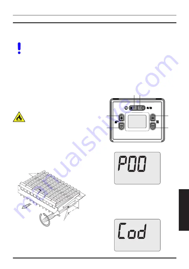
•  Remove the front and side panels as 

shown in section "Maintenance" on page 

55.

•  Remove the movable wall from the sealed 

chamber.

•  Remove the front panel from the combus-

tion chamber and the burner in Figure 8.1.

Figure 8.1

A

A

•  Convert the type of gas by correctly re-

placing the burner nozzles and gaskets.

•  Reassemble the burner Figure 8.1, the 

front combustion chamber panel and the 

movable wall of the sealed chamber.

•  Restore electric power to the boiler.

The boiler is factory set to operate with 

natural gas (G20).

To set boiler operation to 

LPG gas (G31)

carry out the following settings:

• 

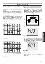
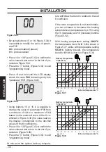
Enter  “programming  mode”  by  holding 

down buttons 17 and 18 for 5 seconds at 

the same time (Figure 8.2). The code 

P00


appears on the display, indicating entry 

into “parameter P00” (Figure 8.3).

Figure 8.2

12

13 

15 

16 

17 

18 

Figure 8.3

bar

RESET

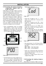
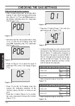
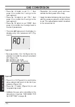
•  Scroll through the various parameters us-

ing 12 or 13 until the LCD display shows 

the message 

Cod

, indicating entry into 

“parameter  Cod”  (Figure  8.4),  and  then 

displays three dashes “

- - -

”.

Figure 8.4

bar

RESET

Summary of Contents for RINNOVA M290E.24CM

Page 1: ...User manual and installation instructions RINNOVA...

Page 2: ...e g injuries or bruises DANGER Instructions marked with this symbol must be observed to avoid electrical accidents electrocution DANGER Instructions marked with this symbol must be observed to avoid t...

Page 3: ...tart up the appliance as it may be dangerous Contact your retailer or the nearest authorised service centre Installation must be carried out by qualified personnel who are responsible for compli ance...

Page 4: ...age caused by the water released when the safety valve opens if it is not correctly connected to a drainage system Make sure that the installer has connected the condensate siphon drain to a specific...

Page 5: ...37 5 12 Installing the external temperature sensor 38 5 13 Electrical connection between the boiler and the external sensor 38 5 14 Enabling operation with the external sensor and setting the K coeffi...

Page 6: ...e DHW inlet The figures in this manual only show one of the possible ways of installing cocks pipes and fit tings Figure 1 2 2 3 4 5 6 7 8 11 10 9 2 Gas supply label 3 Heating circuit filling cock 4 H...

Page 7: ...cates a volatile error The boiler is reactivated automatically once the fault has been resolved The symbol indicates that the boiler can be restarted directly by the user by pressing the re set button...

Page 8: ...ot flash LCD FUNCTION E22 Heating delivery tem perature between 90 C and 100 C E25 Boiler in antifreeze E26 Gas valve fault E28 Tank NTC probe failure E50 Communication with remote control lost E52 Ma...

Page 9: ...in section Antifreeze protec tion on page 13 2 2 Ignition The boiler cocks and the cocks used during installation must be open Figure 2 1 Figure 2 1 Open position Power the boiler by turning on the tw...

Page 10: ...eating delivery hot water temperature and the symbol flash The display background lights up Figure 2 7 Figure 2 7 bar RESET Adjusting the heating temperature based on the outdoor temperature without e...

Page 11: ...s is pressed the set value is displayed The second time it is pressed the value can be changed Signal on the LCD display the set value of the domestic hot water and the symbol flash The display backgr...

Page 12: ...bar RESET In OFF mode the antifreeze protection is active If the boiler will be inactive for a long period of time Disconnect the boiler from the electric power supply Close the boiler cocks Figure 2...

Page 13: ...m thermostat is installed If a radiator or convector does not heat up check if there is any air in the system and make sure that the cock is open If the room temperature is too high do not adjust the...

Page 14: ...an error code flashes on the display and the symbol is shown it is a volatile lockout The boiler is reactivated automatically once the fault has been resolved see General LCD char acteristics on page...

Page 15: ...2 and call a techni cian from the authorised service centre 3 7 Displays in INFO mode INFO mode is used to view boiler status in formation In the case of a boiler malfunc tion provide this information...

Page 16: ...16 INSTALLATION TECHNICAL SPECIFICATIONS 4 TECHNICAL SPECIFICATIONS 4 1 Assembly view Figure 4 1 20 37 40 21 31 3 33 39 35 34 26 41 30 11 23 9 22 24 32 25 10 19 36 46 47 45 42...

Page 17: ...s cock 7 Domestic hot water inlet pipe 8 Heating return pipe 9 Heating circuit safety valve discharge pipe 10 Heating circuit drain cock 11 Heating circuit pressure gauge 19 Heating NTC Max temperatur...

Page 18: ...low voltage ambient thermostat cable or remote control optional elec tric power supply cable 32 Heating pressure switch 33 DHW exchanger 34 Three way valve 35 Three way valve plug 36 Fan 37 Flue gas...

Page 19: ...4 g v gr gr n n c m g v M COM 1 NO 3 b b b c c n n c 2 5 7 8 9 10 11 12 1 3 4 6 a orange b white c blue g yellow gr grey m brown n black r red v purple g v yellow green 1 Electrical power supply 4 Pu...

Page 20: ...3 Heat loss at the chimney with burner off T 50 C Pfbs 0 2 Heat loss towards the environment through the casing with the burner operating Pd 0 9 NOx class 2 Weighted NOx mg kWh 168 ppm 95 Heating Adju...

Page 21: ...nition pressure Methane G20 Pa 900 mbar 9 0 Propane G31 Pa 2520 mbar 25 2 Nozzles N mm 100 Methane G20 11 130 Propane G31 11 78 Chimney design Max flue gas temperature C 123 Min flue gas temperature C...

Page 22: ...5 2 Heat loss at the chimney with burner off T 50 C Pfbs 0 2 Heat loss towards the environment through the casing with the burner operating Pd 1 5 NOx class 2 Weighted NOx mg kWh 179 ppm 101 Heating A...

Page 23: ...nition pressure Methane G20 Pa 830 mbar 8 3 Propane G31 Pa 2490 mbar 24 9 Nozzles N mm 100 Methane G20 14 130 Propane G31 14 77 Chimney design Max flue gas temperature C 111 Min flue gas temperature C...

Page 24: ...9 Heat loss at the chimney with burner off T 50 C Pfbs 0 2 Heat loss towards the environment through the casing with the burner operating Pd 1 NOx class 2 Weighted NOx mg kWh 169 ppm 96 Heating Adjus...

Page 25: ...ition pressure Methane G20 Pa 720 mbar 7 2 Propane G31 Pa 2320 mbar 23 2 Nozzles N mm 100 Methane G20 15 130 Propane G31 15 78 Chimney design Max flue gas temperature C 125 Min flue gas temperature C...

Page 26: ...closure of thermostatic valves or circuit cocks the by pass guarantees a min imum circulation of water inside the primary condensate exchanger The by pass is calibrated for a differential pressure of...

Page 27: ...t kits pro vided by the manufacturer as they are an integral part of the boiler For LPG gas Propane G31 the installa tion must also comply with the requirements of the distributing companies and with...

Page 28: ...cautions in order to prevent damaging the boiler Do not add antifreeze or anticorrosion products to the heating water in the wrong concentrations or use those with chemi cal physical characteristics t...

Page 29: ...Gas G 3 4 MF 16 18 ES 12 14 RR 16 18 G1 2F 3 bar safety valve fitting 5 6 Boiler assembly Remove the protective caps from the boil er pipes Hook the boiler onto the bracket Screw the cock on the boile...

Page 30: ...tall one or more condensate collection kits where necessary Figure 5 5 1 5 The following kits are available for connec tion to the boiler Wall mounted flue gas outlet kit Figure 5 8 A Coaxial duct 60...

Page 31: ...kit is used to separate the flue gas out let from the air suction The terminals can be inserted in exhaust flues designed for this purpose or dis charge flue gas or intake air directly on the wall The...

Page 32: ...lengths between 15 m and 30 m 47 mm 50 mm Figure 5 11 M290E 28CM Twin split pipes 80 80 mm Diaphragm Flue gas Air For lengths between 0 5 m and 15 m 38 mm no For lengths between 15 m and 30 m 47 mm no...

Page 33: ...nsation products When dimensioning the ducts take into ac count the residual pressure difference at the fan Useful static pressure at nominal heat input 24 kW 75 Pa 28 kW 106 Pa 32 kW 93 Pa Overheated...

Page 34: ...vided in this sec tion The diaphragm must be positioned as shown in Figure 5 7 Coaxial 80 125 mm 90 and 45 elbows are available that reduce the total max length of the ducts by For a 45 elbow loss 0 5...

Page 35: ...gas air diaphragms and the maximum lengths refer to figures Figure 5 9 Figure 5 10 Figure 5 11 and Figure 5 12 90 and 45 elbows are available that re duce the total max length of the ducts by For a 4...

Page 36: ...1 Connect the earth wire yellow green to an effective earthing system Figure 5 21 Electric power supply TA The earth wire must be longer than the electric power wires The unit s electric power supply...

Page 37: ...in Figure 5 22 to con nect the remote 5 11 Enabling of operation with re mote control optional The boiler leaves the factory with a room thermostat enabled To change this setting to remote control ent...

Page 38: ...s or walls where mould forms Installation near fans drain outlets or chimneys 5 13 Electrical connection between the boiler and the external sen sor To connect the external sensor to the boiler use el...

Page 39: ...5 K 1 0 K 1 5 K 2 0 K 2 5 K 3 0 K A52 30 25 20 15 10 5 0 5 10 15 20 Figure 5 31 External temperature C 45 50 55 60 65 70 75 80 85 Delivery temperature C 50 80 C 30 25 20 15 10 5 0 5 10 15 20 K 0 2 K...

Page 40: ...ients Press 12 or 13 Figure 5 32 to confirm the value entered and return to the list of pa rameters Figure 5 36 Press the 17 button Figure 5 32 to exit programming mode At this point the system delive...

Page 41: ...40 bar RESET Scroll through the various parameters us ing 12 or 13 until the LCD display shows the message Cod indicating entry into parameter Cod Figure 8 4 and then displays three dashes Figure 5 41...

Page 42: ...12 to confirm the 9 and go to the next segment Press the 16 button to set 1 9 8 then press 12 to confirm the 8 and go back to the list of parameters Press 12 and hold until the LCD display shows the c...

Page 43: ...nd return to the list of pa rameters Figure 5 49 Press the 17 button Figure 5 47 to exit programming mode 5 18 Selecting re ignition frequency When the boiler functions in normal on off heating mode t...

Page 44: ...tor creates a reduced load loss zone that makes the primary cir cuit and secondary circuit hydraulically in dependent In this case the flow rate that passes through the circuits depends exclusively on...

Page 45: ...aulic systems High temperature zone low temperature zone Figure 5 55 S High temp zone Low temp zone External temp probe High temperature zone 2 low temperature zones Figure 5 56 S Low temp zone 1 Low...

Page 46: ...e body see section Removing the body panels on page 55 Open the installed water cocks Open one or more hot water cocks to bleed the pipes Loosen the automatic bleed valve cap 23 in Figure 6 3 Figure 6...

Page 47: ...osition Check the correct operation of the boiler both in DHW mode and in heating mode Check the gas pressures and flow rates as shown in section CHECKING THE GAS SETTING on page 48 of this manual Che...

Page 48: ...l data M290E 24CM on page 20 Techni cal data M290E 28CM on page 22 and Technical data M290E 32CM on page 24 Fully close the tapping point 29 in Figure 7 8 Check maximum burner pressure Open the tappin...

Page 49: ...lue measured with that shown in the Maximum gas pressure at burner tables To calibrate the pressure at the burner turn the large brass hexagonal nut of the modulating operator 28 MAX in Figure 7 8 tur...

Page 50: ...t minimum out put Press the 12 button Figure 7 2 to confirm the value entered and activate the function Figure 7 15 Figure 7 15 bar RESET Press the 17 button Figure 7 2 to exit pro gramming mode Figur...

Page 51: ...Each time after measuring the gas pressure properly close all tap ping points that were used 27 and 29 in Figure 7 8 After each gas adjustment the valve adjustment components must be sealed 7 3 Setti...

Page 52: ...t the room thermostat is in the heat request position Draw off an abundant amount of DHW by opening the taps Enter programming mode by holding down buttons 17 and 18 for 5 seconds at the same time Fig...

Page 53: ...nt panel from the combus tion chamber and the burner in Figure 8 1 Figure 8 1 A A Convert the type of gas by correctly re placing the burner nozzles and gaskets Reassemble the burner Figure 8 1 the fr...

Page 54: ...15 or 16 Figure 8 2 it is possible to modify the value of parameter A01 Figure 8 6 00 Methane gas G20 01 Propane gas LPG G31 Figure 8 6 bar RESET Press 12 or 13 Figure 8 2 to confirm the value entere...

Page 55: ...boiler operation problems will not be covered by the standard warran ty Before performing any cleaning or mainte nance operation or before opening or re moving the boiler panels isolate the unit from...

Page 56: ...e heating circuit drain cock 10 indicated in Figure 9 4 Figure 9 4 OPEN CLOSED Heating circuit drain cock 10 To make draining easier unscrew the au tomatic bleed valve cap 23 in Figure 9 5 Figure 9 5...

Page 57: ...e a technician from an authorised ser vice centre periodically check the condition of the flue gas exhaust duct the air duct and the efficiency of the flue gas safety circuit at least once a year To c...

Page 58: ...W 33 9 Nominal efficiency 93 1 Combustion efficiency 94 1 Air index n 1 6 Composition of CO2 fumes 7 2 Composition of O2 fumes 8 1 Flue gas temperature C 125 Values refer to tests with 60 100 1 m conc...

Page 59: ...he 12 button Figure 9 11 to con firm the value entered and activate the function Figure 9 16 Figure 9 16 bar RESET To exit the chimney sweeper reset the value of parameter P06 to 00 or wait 15 minutes...

Page 60: ...ame ter A01 Figure 9 22 00 Methane gas G20 01 Propane gas LPG G31 Figure 9 22 bar RESET Press 12 or 13 Figure 9 18 to confirm the value entered and return to the list of pa rameters Figure 9 21 Press...

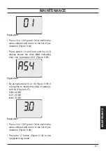
Page 61: ...ows the code A54 indicating entry into parameter A54 Figure 9 26 Figure 9 26 bar RESET By using buttons 15 or 16 Figure 9 18 it is possible to modify the value of parame ter A54 Figure 9 27 3 0 24 kW...

Page 62: ...erials where possible The installer must dispose of the packaging used to transport the boiler Please observe the regulations currently in force regarding re cycling and disposing of the boiler and an...

Page 63: ......

Page 64: ...ny time and without notice Product warranty pursuant to Leg Decree no 24 2002 BSG Caldaie a Gas S p a Registered office sales and administrative headquarters plant and technical support 33170 PORDENON...

Reviews: