Installation
24
total (wet) load. Refer to the weight given in the
technical data tables specific for each model.
6.4
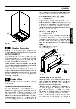
Overall dimensions
A --- air intake/flue outlet pipe (co---axial)
B --- flue outlet pipe ø 80 mm (twin kit)
C --- air intake pipe ø 80 mm (twin kit)
ø80
ø80
ø100
400
200
24
5
19
6
80
3
70
0
35
115
142
16
31
60
60
100
257
200
65
64
52
65
50
120
350
217
A, B and C
Boile
rf
ron
t
B
A
C
Gas
D.h.w.
C.h.
Cold
C.h.
return
flow
outlet
water
inlet
Electric
connection
area
Condensate
drain connection
area
120
ø80
C
Fig. 6.2 (all dimensions in mm)
6.5
Joints
Functions
Pipe sizes (o.d)
Gas, c.h. return, c.h. flow
ø 22
D.c.w. inlet
ø 15
D.h.w. outlet
ø 15
Pressure relief valve
ø 15
Condensate drain
ø 25 (plastic)
Tab. 6.1 (sizes in mm o.d.)
6.6
Mounting the boiler
1 Take the protective caps off the boiler pipe-
work.
2 Thoroughly clean the connections.
3 Mount the boiler on its bracket.
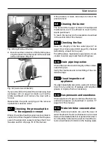
4 Fix the c.h. valves A and gas cock B (¾”) to the
boiler using the ¾” gaskets (Fig. 6.3)
5 Fix the ø 22 mm pipes C (c.h. circuit) to the c.h.
valves A and the ø 22 mm pipe D (gas) to the
cock B using the ¾” gaskets.
6 Repeat the above procedure for the d.c.w. inlet
utilising the ½” cold water inlet valve E, the ø 15
mm copper tail F with its connection nut and
two ½” gaskets.
7 Fix the ø 15 mm copper tail G with the ½” con-
nection nut and a ½” gasket.
C
A
A
B
D
C
E
F
G
Fig. 6.3
8 Connect the pipe H (Fig. 6.4) from the pres-
sure relief valve to the safety discharge pipe-
work.
9 Fit the condensate drain 11 (Fig. 6.4) in the air
brake connected to the drainage pipework.
See also section 5.7 in this manual.
INST
ALLA
TI
ON


