Maintenance
37
23
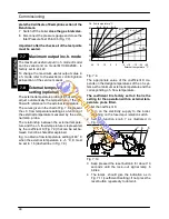
Fig. 9.4
9.5
Combustion analysis check
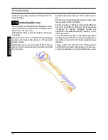
If it is necessary to carry out a combustion analysis
remove the plugs indicated in Fig. 7.5.
Reference figures are given in the sections 4.5 of
this manual .
If the analysis results are not within the reference
figures in the
Service manual
, section
Gas valve ---
Adjustment.
9.6
Cleaning the condensing heat
exchanger and burner
F
M
M
D
H
E
Fig. 9.5
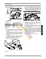
To remove the burner---fan group D (Fig. 9.5):
1 Take off the front and side panels of the case.
2 Remove the sealed chamber lid.
3 Disconnect the connectors of the ignition elec-
trodes E and detection electrode F (Fig. 9.5).
G
I
J
Fig. 9.6 (right side of the fan)
4 Disconnect the rubber pipe G (Fig. 9.6).
5 Unscrew the gas connector H (Fig. 9.5).
6 Remove the fixing fork I and remove the gas
pipe J (Fig. 9.6).
K
L
Fig. 9.7 (rear view of the fan)
7 Disconnect the connector of the fan K by pres-
sing the plastic hook L placed on the rear side
of the connector (Fig. 9.7).
8 Remove the nuts M (Fig. 9.5) and the burner---
fan group D.
M
A
INTE
NA
NCE


