background image

- 10 -

USE

INSTRUCTIONS FOR USE

INSTRUCTIONS FOR USE

2.1  Warnings

Biasi Uk Ltd support the Benchmark initia-

tive. The Benchmark Checklist is located 

at the back of this manual and should be 

completed by the Installing/Commission-

ing Engineer and handed over to the User 

for future reference by other visiting Engi-

neers. Also included is the Service Interval 

Record card that should be completed by 

the Service Engineer following the annual 

service maintenance of the boiler and sys-

tem.

All Gas Safe Registered Installers carry a 

Gas Safe ID card, and have a registration 

number. Both should be recorded in your 

Benchmark Checklist. You can check your 

Installer is registered by calling Gas Safe 

direct on 0800 408 5500, or go on line at 

www.GasSafeRegister.co.uk.

In order to guarantee safety and correct op-
eration, it is essential that all the tests are 
carried out by a competent and responsible 
service engineer before lighting up the boiler.
The tests are described in the installation in-
structions in section 7 commissioning.
Ensure  that  the  c.h.  circuit  is  regularly  filled 
with water (even if the boiler is only used for 
d.h.w. supply) checking that the pressure indi-
cated on pressure gauge 4 is not lower than 
that shown in Fig. 2.2.
If the pressure reading on the pressure gauge 
is below that shown in Fig. 2.2, then the sys-
tem  will  require  topping  up.  A  filling  loop  is 
normally provided by the Installer for this pur-
pose.

If you are in any doubt regarding this pro-

cedure you are advised to contact your In-

staller or an Approved Engineer.

This appliance is provided with a built in anti-
freeze system that operates the boiler when 

the temperature is below 5 °C.
Therefore, when the boiler is not lit or used 
in cold weather, with consequent risk of freez-
ing 

do not switch off the boiler at the fused 

spur isolation switch or close the gas inlet 

cock.

When you do not expect to use the boiler for 
a long period and the boiler is not to be used 
for frost protection then follow the instructions 
given in section "Extinguishing" to page 12.

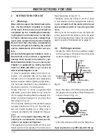
2.2  Refilling procedure

•  Isolate the boiler from the electrical supply 

at the fused spur. Reconnect the filling loop 
as demonstrated in Fig. 2.1.

Fig. 2.1

Control

valve

Double 

check valve

Temporary

connection

Supply pipe

(cold water 

inlet)

Control valve

C.h. return pipe

•  Open the valves of the filling loop and watch 

the gauge until it reaches normal filling pres-
sure as shown in Fig. 2.2.

Fig. 2.2

Normal 

filling

pressure

4

•  Close the valves and remove the filling loop.

If you experience any difficulty with the op-

Summary of Contents for RIVA ADVANCE HE M110B.24SR/C

Page 1: ...Wall hung fanflue roomsealed high efficiency gas boiler User manual and Installation instructions RIVA ADVANCE HE Models G C Appl No M110B 24SR C 41 583 07...

Page 2: ...water systems in the UK and to encourage regular servicing to optimise safety efficiency and performance Benchmark is managed and promoted by the Heating and Hot water Industry Council For more infor...

Page 3: ...otified to Local Area Building Control either directly or through a Competent Persons Scheme A Building Regulations Compliance Certificate will then be issued to the customer who should on receipt wri...

Page 4: ...pply system com patible with its performance and output can be used only for those purposes for which it has been specially designed must not be touched by children or by those unfamiliar with its ope...

Page 5: ...al attention must be sought following eye contact or prolonged reddening of the skin Thermostat Temperature gauge Description Sealed phial and capillary containing liquid Known hazards irritating to s...

Page 6: ...and installation debris It is also sensible to initially fire and commission the boiler before connecting any external controls such as a room thermostat By following this procedure if you have a subs...

Page 7: ...6 Lighting the boiler 39 7 7 Checking the gas supply pressure 39 7 8 Maximum output in c h mode 41 7 9 External temperature probe setting optional 41 7 10 Checking the ignition device 42 7 11 Checking...

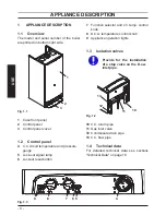
Page 8: ...essure gauge 5 Lock out signal lamp 6 Lockout reset button 7 Function selector and c h temp control knob 8 D h w temperature control knob 9 Appliance operation lights 1 3 Isolation valves Provide for...

Page 9: ...ombination observed is not included in the above table a fault may be indicated Reference should be made to the following table In this case switch off the boiler as de scribed in section Extinguishin...

Page 10: ...ed on pressure gauge 4 is not lower than that shown in Fig 2 2 If the pressure reading on the pressure gauge is below that shown in Fig 2 2 then the sys tem will require topping up A filling loop is n...

Page 11: ...ance operation light 9 Fig 2 4 will flash every 4 seconds stand by condition To operate the boiler position the function selector 7 as in Fig 2 4 The appliance op eration light 9 will flash every 2 se...

Page 12: ...temperature In this case the boiler must be properly set by the Installer section External temperature probe setting optional to page 40 and the c h flow temperature control knob 7 must be positioned...

Page 13: ...he obstruction by pouring hot water over the exposed pipe an cleaning any blockage from the end of the pipe If this fails to remedy the problem the assist ance of a Gas Safe registered installer or in...

Page 14: ...below the correct setting If required top up the system correctly as described in the section Refilling proce dure to page 10 Bleed any air present in the radiators if necessary If the pressure on th...

Page 15: ...15 INSTALLATION TECHNICAL INFORMATION 4 TECHNICAL INFORMATION 4 1 Overview Fig 4 1 33 17 31 27 26 22 18 24 15 21 25 28 32 14 29 23 30 20 19 16 34...

Page 16: ...w pipe 14 Condensing heat exchanger 15 C h temperature probe NTC 16 Condensing heat exchanger 17 Safety thermostat 18 Flame detecting electrode 19 Transformer 20 Air manifold 21 C h pressure relief va...

Page 17: ...rap 29 Fan 30 Spark generator 31 Ignition electrode 32 Burner 33 Flue temperature probe NTC 34 Safety thermal fuse 35 Gas valve inlet pressure test point 36 Gas valve outlet pressure test point 37 C h...

Page 18: ...ar 2 5 Minimum pressure kPa 30 bar 0 3 Available head in 1000 l h kPa 23 bar 0 23 Seasonal efficiency C band A 90 2 Gas supply pressures Gas Pa mbar Natural G20 Nom 2000 Min 1700 17 Max 2500 25 Propan...

Page 19: ...um heat input of 6 0 kW A E Other flue gas figures At nominal heat input non condensing O2 content 4 3 4 3 CO content ppm 200 Exhaust temperature D C 85 Other specifications Height mm 803 Width mm 400...

Page 20: ...the boiler in the event that the flow around the central heating circuit is restricted due to closure of thermostatic or system control valves 4 5 Expansion vessel Note this boiler is designed for ope...

Page 21: ...mplete a Declaration of Conformity to indicate compliance to I S 813 2002 This appliance must be installed by a com petent person in accordance with the Gas Safety installation Use Regulations 5 1 Rel...

Page 22: ...tion that might occur to building products in the vicini ty In cold and or humid weather water vapour may condense on leaving the flue terminal the effect of such steaming must be consid ered Pluming...

Page 23: ...compartment it is not necessary to provide additional ventilation for cooling for this particular product Howev er consideration must be given to clearance requirements for maintenance section Pre cau...

Page 24: ...d have a gradient to ensure air is carried naturally to air release points and water flows naturally to drain taps The appliance has a built in automatic air release valve it should be ensured as far...

Page 25: ...as frequent filling of the system could cause pre mature scaling of the heat exchanger 5 9 Water treatment C h circuit Where a new boiler is fitted to a new system with either plastic or copper pipes...

Page 26: ...ON GENERAL REQUIREMENTS The point of connection to the electricity sup ply must be readily accessible and adjacent to the appliance except were the appliance is installed in a bathroom this must then...

Page 27: ...er Refer to section Electrical connections to page 31 in this chapter for the electrical connections In no circumstances will the manufac turer be held responsible if the warnings and instructions con...

Page 28: ...ions for fitting the exhaust fume duct are complied with refer to the leaflet includ ed with the flue kit packed separately Utilise the paper template supplied with the boiler to determine the fixing...

Page 29: ...in the air brake connected to the drainage pipework See also section Condensate drain to page 23 Fig 6 4 L 12 6 7 Fitting the flue system Refer to the assembly instructions con tained within the chose...

Page 30: ...and the equivalent flue length must not ex ceed 10 metres Elbows 45 90 Fig 6 5 C Coaxial 60 100 mm Elbow kits enable the standard flue kits to be offset to overcome obstructions or ensure the correct...

Page 31: ...ended to a total overall maximum per missible length of 10 m Optional 45 and 90 elbows can be used to offset the flue route Each additional elbow reduces the overall acceptable length of the flue syst...

Page 32: ...M N O N Remove the side panels or move the lower part of the side panels as indicated in Fig 6 11 and pull the control panel When com pletely pulled out the panel can rotate 45 downwards to facilitate...

Page 33: ...own in Fig 6 14 or Fig 6 15 Fig 6 14 Power supply terminal block External controls terminal block T Room thermostat L N 3 2 1 230V rating Do not connect live wires to ter minals to which the room ther...

Page 34: ...c control of heat ing and hot water Fig 6 19 and Fig 6 20 are divided in two parts The upper shows the single compo nents used on the diagrams with their con nection to the 10 way junction box The bol...

Page 35: ...ol terminal block Room thermostat A B 5 4 Cylinder thermostat C 1 2 8 7 6 GY WH OR GRYE BU 2 3 8 5 7 MAINS 230V a c Switched 3 Amp fused spur L N 2 3 1 Programmer HTG HW OFF HW ON L N 2 1 4 6 7 Power...

Page 36: ...hermostat link Room thermostat A B 4 5 Cylinder thermostat C 1 2 8 7 6 GY WH OR GRYE BU 2 3 8 5 7 MAINS 230V a c Switched 3 Amp fused spur L N 2 3 1 Programmer HTG HW OFF HW ON L N 2 1 4 6 7 Power sup...

Page 37: ...ary electrical system checks to en sure electrical safety shall be carried out by a competent person i e polarity earth con tinuity resistance to earth and short circuit If a fault has occurred on the...

Page 38: ...ing procedure must be in line with BS7593 2006 Treatment of Water in d h w c h Systems When the installation and second fill ing are completed turn on the c h sys tem and run it until the temperature...

Page 39: ...h every 2 seconds Fig 7 6 9 7 6 5 The boiler will now go through an ignition sequence and the burner will light If after four ignition attempts about four minutes the boiler fails to light the boiler...

Page 40: ...witching on the fused spur isolation switch The appliance operation light 9 will flash every 4 seconds Set the function knob 7 as illustrated in Fig 7 8 Fig 7 8 9 7 6 5 Read the inlet pressure value a...

Page 41: ...n Fig 7 9 Fig 7 9 20 30 40 50 60 70 80 External temperature C C h flow temperature C 20 15 10 5 0 5 10 15 20 25 K 4 K 3 K 2 K 1 K 0 5 K 1 5 K 6 The appropriate value of the coefficient K depends on th...

Page 42: ...or a coefficient K set to 1 5 is illustrated in Fig 7 14 Fig 7 14 20 30 40 50 60 70 80 External temperature C C h flow temperature C 20 15 10 5 0 5 10 15 20 25 K 1 5 15 C 15 C 7 10 Checking the igniti...

Page 43: ...use and adjustment of all system controls this will ensure the great est possible fuel economy Explain the function and use of the function selector Explain and demonstrate the function of time and t...

Page 44: ...8 2 Procedures Check that the gas cock 11 in Fig 8 1 fitted under the boiler is turned off and the appliance is switched off at the mains isolat ing spur Fig 8 1 11 Closed position Remove the front pa...

Page 45: ...7 6 5 Disconnect the C h temperature probe NTC 15 in Fig 8 6 Fig 8 6 15 Keep pressed the reset button 6 for about 10 seconds until the lock out signal lamp 5 blinks Connect the C h temperature probe...

Page 46: ...Fig 8 8 By turning the knob 8 the lock out signal lamp 5 blinks quickly 2 per seconds indicating that the setting has changed and must be memorised To memorize the setting keep pressed the reset butto...

Page 47: ...on switch adjacent to the appliance and turn off the gas cock before carrying out any procedures whatsoever for cleaning maintenance opening or dismantling boiler panels The Engineer should complete t...

Page 48: ...e front and side panels of the case Remove the sealed chamber lid Disconnect the connectors of the ignition electrodes E and detection electrode F Fig 9 5 Fig 9 5 D E F G H H Disconnect the rubber pip...

Page 49: ...rations de scribed in the section Cleaning the con densing heat exchanger and burner to page 47 9 8 Checking the flue Have the integrity of the flue outlet pipe 39on page 17 air intake pipe 40on page...

Page 50: ...ect the customer s statutory rights If yes and if required by the manufacturer has a water scale reducer been fitted Condensing Boilers only The condensate drain has been installed in accordance with...

Page 51: ...er Name Company Name Telephone No Gas Safe Register No Comments Signature Date Engineer Name Company Name Telephone No Gas Safe Register No Comments Signature Date Engineer Name Company Name Telephone...

Page 52: ...1796215290 17962 1529 0 0312 52A5 UK Biasi UK Ltd Commercial Road Leamore Enterprise Park WALSALL WS2 7NQ Sales Tel 01922 714600 Tech Service Tel 01922 714636 www biasi co uk 16 01 2012 N...

Reviews: