- 32 -
INST
ALLA
TION
INSTALLATION
In the last section, the fumes are expelled
through a vertical section.
Extensions and elbows can be added to ex-
tend the kit’s length.
Maximum equivalent length “
a
+
b
” (Fig. 6.9)
of 15 metres can be achieved utilising ex-
tensions.
Each additional elbow reduces the overall
acceptable length of the flue system as fol-
lows:
For the elbow of 45° (60/100 mm) loss 0,5 m
For the elbow of 90° (60/100 mm) loss 1 m
For the elbow of 45° (60 mm) loss
0,65 m
For the elbow of 90° (60 mm) loss
0,85 m
6.9 Electrical connections
Connection to the electricity supply
• Remove the front panel of the case (see
the section "Dismantling the external pan-
els" to page 46).
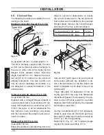
• Remove the screws M and N (Fig. 6.10).
• Loosen the screws O.
Fig. 6.10
M
N
O
N
• Remove the side panels or move the lower
part of the side panels as indicated in Fig.
6.11 and pull the control panel. When com-
pletely pulled out, the panel can rotate 45°
downwards to facilitate the operations on
the internal parts.
Fig. 6.11
• Loosen the screws P and remove the ser-
vice panel (Fig. 6.12).
Fig. 6.12
P
For the electrical connection to the boiler
use electric wires which conform to the cur-
rent regulations, with flexible cord, each
core having a cross section area
not less
than 0,75 mm
2
.
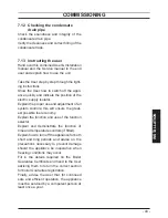
• Connect the electrical supply flexible
cord coming from the fused spur isolation
switch to the power supply terminal block
of the boiler (Fig. 6.13) keeping the same
connections for the live (brown wire) and
the neutral (blue wire). External 3 A fuse or
fused plug with same current rating is rec-
ommended.
Do not connect live wires to
terminals to which the room thermostat
must be connected.
• Connect the earth wire (yellow/green).


