background image

- 12 -

USE

INSTRUCTIONS FOR USE

contact your installer or Service Agent.
Adjustment of the boiler temperature alters 
the gas flow at the burner according to the 
thermal demand in the system. So it is usual 
to see the burner lit at the minimum level for 
more or less long periods.

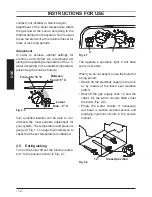
Adjustment

In  order  to  achieve  optimal  settings  for 
economy and comfort, we recommend ad

-

justing the operating temperature of the c.h. 
water according to the outside temperature, 
positioning the knob as follows:

Fig. 2.6

From 5 to 15 °C

Between

- 5 and +5 °C

Lower

than - 5 °C

Your  qualified  installer  will  be  able  to  rec

-

ommend  the  most  suitable  adjustment  for 
your system. The temperature and pressure 
gauge (

4, 

Fig. 1.3 on page 8) will allow you to 

check that the set temperature is obtained.

2.5 

Extinguishing

To turn the boiler off set the function selec

-

tor 7

 to the position shown in Fig. 2.7

.

Fig. 2.7

The  appliance  operation  light  9  will  flash 

every 4 seconds.

When you do not expect to use the boiler for 
a long period:

• 

Switch off the electricity supply to the boil

-

er,  by  means  of  the  fused  spur  isolation 
switch;

• 

Shut  off  the  gas  supply  cock  12

 and the 

valves  for  the  water  circuits  fitted  under 
the boiler (Fig. 2.8).

• 

Empty  the  water  circuits,  if  necessary, 
as shown in section 

General access and 

emptying hydraulic circuits

 in the service 

manual.

Fig. 2.8

12 

Closed position 

Summary of Contents for RIVA PLUS HE 24S ERP

Page 1: ...nflue roomsealed high efficiency gas boiler User manual and Installation instructions Riva Plus HE ERP Models G C Appl No RIVA PLUS HE 24S ERP 41 583 31 SYSTEM BOILER RIVA PLUS HE 28S ERP 41 583 32 SY...

Page 2: ...t water systems in the UK and to encourage regular servicing to optimise safety efficiency and performance Benchmark is managed and promoted by the Heating and Hot water Industry Council For more info...

Page 3: ...otified to Local Area Building Control either directly or through a Competent Persons Scheme A Building Regulations Compliance Certificate will then be issued to the customer who should on receipt wri...

Page 4: ...water to a temperature less than boiling point must be connected to a central heating system and or a hot water supply system com patible with its performance and output can be used only for those pu...

Page 5: ...brasion In general normal handling and use will not present high risk follow good hygiene practices wash hands before touching eyes consuming food drinking or using the toilet First aid Medical attent...

Page 6: ...on the boiler before connecting any external controls such as a room thermostat By this method if you have a subsequent problem following the addition of an external control you can eliminate the boil...

Page 7: ...ate pipe and traps 44 7 6 Lighting the boiler 44 7 7 Checking the gas pressure at the burner 45 7 8 Checking the burner ignition 46 7 9 Checking the ignition device 46 7 10 Checking the flue system 47...

Page 8: ...p 6 Lockout reset button 7 Function selector and c h temp control knob 8 Service knob 9 Appliance operation lights The service knob 8 is useless for the normal operation of the boiler 1 3 Isolation va...

Page 9: ...imary circuit no water or low c h pressure Faulty primary circuit absence of flow Faulty air pressure sen sor Lack of burner ignition no ignition signal from the full sequence ignition device Safety t...

Page 10: ...h w supply checking that the pressure indicated on pressure gauge 4 is not lower than that shown in Fig 2 2 If the pressure reading on the pressure gauge is below that shown in Fig 2 2 then the system...

Page 11: ...of the boiler are open Fig 2 3 Fig 2 3 Open position Turn on the electricity supply to the boil er switching on the fused spur isolation switch The appliance operation light 9 Fig 2 4 will flash every...

Page 12: ...l be able to rec ommend the most suitable adjustment for your system The temperature and pressure gauge 4 Fig 1 3 on page 8 will allow you to check that the set temperature is obtained 2 5 Extinguishi...

Page 13: ...ing any blockage from the end of the pipe If this fails to remedy the problem the assis tance of a Gas Safe registered installer or in IE a competent person should be sought 3 4 Periodic maintenance F...

Page 14: ...e to page 10 Bleed any air present in the radiators if nec essary If the pressure on the temperature and pressure gauge has gone down It is necessary to top up the appliance with water again so as to...

Page 15: ...15 INSTALLATION TECHNICAL INFORMATION 4 TECHNICAL INFORMATION 4 1 Overview Fig 4 1 17 19 31 27 26 23 29 28 24 16 20 25 21 30 18 14 15 22 32 33...

Page 16: ...ve 14 Fan 15 Air pressure sensor test points 16 Air pressure sensor 17 Flue temperature probe NTC 18 Condensing heat exchanger 19 Safety thermostat 20 C h temperature probe NTC 21 Condensate trap 22 M...

Page 17: ...ustion chamber over heat 29 Flame detecting electrode 30 Burner 31 Ignition electrodes 32 Combustion chamber 33 Primary heat exchanger 34 Modulation operator 35 Gas valve outlet pressure test point 36...

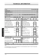
Page 18: ...sure kPa 30 bar 0 3 Available head in 1000 l h kPa 25 bar 0 25 Seasonal efficiency G20 88 1 Seasonal effciency G30 G31 C 89 1 to the minimum useful output Gas supply pressures Gas Pa mbar Natural G20...

Page 19: ...2 content with gas G20 7 9 O2 content with gas G20 6 8 CO content with gas G20 ppm 52 0 Exhaust temperature E C 60 0 NOx class 2 0 Weighted NOx ppm 94 CO2 contents ch dhw Nominal heat input A E kW 25...

Page 20: ...d heat output and low temperature regime 1 95 4 Auxiliary electricity consumption Other items At full load elmax 0 079 kW Standby heat loss Pstby 0 098 kW At part load elmin 0 065 kW Ignition burner p...

Page 21: ...ssure kPa 30 bar 0 3 Available head in 1000 l h kPa 25 bar 0 25 Seasonal efficiency G20 88 1 Seasonal effciency G30 G31 C 89 1 to the minimum useful output Gas supply pressures Gas Pa mbar Natural G20...

Page 22: ...2 content with gas G20 7 9 O2 content with gas G20 6 8 CO content with gas G20 ppm 53 0 Exhaust temperature E C 60 0 NOx class 2 0 Weighted NOx ppm 90 CO2 contents ch dhw Nominal heat input A E kW 29...

Page 23: ...d heat output and low temperature regime 1 95 2 Auxiliary electricity consumption Other items At full load elmax 0 090 kW Standby heat loss Pstby 0 113 kW At part load elmin 0 075 kW Ignition burner p...

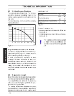
Page 24: ...to closure of the thermostatic valves or system component cocks the by pass valve ensures a mini mum flow of water through the primary heat exchanger 4 6 Expansion vessel Note this boiler is designed...

Page 25: ...ecessary to com plete a Declaration of Conformity to in dicate compliance to I S 813 2002 This appliance must be installed by a competent person in accordance with the Gas Safety installation Use Regu...

Page 26: ...oss at all times The terminal should be located with due regard for the damage or discoloration that might occur to building products in the vi cinity In cold and or humid weather water vapour may con...

Page 27: ...nt 5 6 Ventilation If installed in a cupboard or compartment it is not necessary to provide additional ven tilation for cooling for this particular prod uct However consideration must be given to clea...

Page 28: ...e a gradi ent to ensure air is carried naturally to air release points and water flows naturally to drain taps The appliance has a built in automatic air release valve it should be ensured as far as p...

Page 29: ...use premature scaling of the heat exchanger 5 9 Water treatment C h circuit Where a new boiler is fitted to a new system with either plastic or copper pipes it is im portant the system is fully flushe...

Page 30: ...LLATION 30 INSTALLATION GENERAL REQUIREMENTS supply must be readily accessible and adja cent to the appliance except where the ap pliance is installed in a bathroom this must then be sited outside the...

Page 31: ...tegory III Refer to section Electrical connections to page 36 in this chapter for the electrical connections In no circumstances will the manufac turer be held responsible if the warnings and instruct...

Page 32: ...r template supplied with the boiler to determine the fixing position for the bracket and boiler Securely mount the bracket to the wall using appropriate fixings suitable for the type of wall construct...

Page 33: ...e boiler In the standard horizontal flue kit Fig 6 6 A the flue pipe is angled within the air duct therefore the air duct must be horizontally installed If one or more extensions have to be used they...

Page 34: ...he overall accept able length of the flue systemas follows For the elbow of 45 loss 0 5 m For the elbow of 90 loss 1 m Twin pipe kits 80 mm Fig 6 7 Fig 6 8 Fig 6 7 Type C12 Various twin split pipes ki...

Page 35: ...an 15 m up to 30 m 55 mm Fig 6 9 Air intake adapter Restrictor Gasket Vertical roof kit Fig 6 10 This kit allows vertical termination of the flue pipe through the roof The kit is 1 2 m in length Exten...

Page 36: ...di mensions of the ducts a and b of Fig 6 11 Each additional elbow reduces the overall ac ceptable length of the flue system as follows 45 60 100 mm reduce length by 0 5 m 90 60 100 mm reduce length...

Page 37: ...he same connections for the live brown wire and the neutral blue wire External 3 A fuse or fused plug with same current rating is recommended Do not connect live wires to terminals to which the room t...

Page 38: ...cal supply flexible cord and the external control flexible cord as illustrated in Fig 6 19 Lock the flexible cords in place with the flexible cord clamps Fig 6 19 To the fused spur isolation switch To...

Page 39: ...0 way junction box The bold num bers represent the terminal of the junction box where the component must be con nected to The lower part shows how to realize a sys tem that provides independent timed...

Page 40: ...control terminal block Room thermostat A B 5 4 Cylinder thermostat C 1 2 8 7 6 GY WH OR GRYE BU 2 3 8 5 7 MAINS 230V a c Switched 3 Amp fused spur L N 2 3 1 Programmer HTG HW OFF HW ON L N 2 1 4 6 7...

Page 41: ...Cylinder thermostat C 1 2 8 7 6 GY WH OR GRYE BU 2 3 8 5 7 MAINS 230V a c Switched 3 Amp fused spur L N 2 3 1 Programmer HTG HW OFF HW ON L N 2 1 4 6 7 Power supply L N 2 3 8 External control terminal...

Page 42: ...ut by a competent person i e polarity earth continu ity resistance to earth and short circuit If a fault has occurred on the appliance the fault finding procedure should be followed as specified in th...

Page 43: ...mp release The pump electronic control circuit automati cally releases the pump Turn on the electricity supply to the boiler switching on the fused spur isolation switch The appliance operation light...

Page 44: ...re to run the boiler Fill the built in condensate trap by removing the flue elbow and pour ing a cupful of water into the flue outlet Fig 7 5 Fig 7 5 An alternative to avoid the removal of the flue el...

Page 45: ...led chamber lid Loosen the internal screw 35 Fig 7 8 on the Outlet Pressure Test Point of the Gas Valve and connect a pressure gauge using a suitable hose Set the c h temperature control knob to its m...

Page 46: ...nition pressure registered corresponds to the values as given in the Technical Data Turn off the boiler and reignite it by turning the function selector 7 to the OFF position and then back to that ind...

Page 47: ...he pump has been released open the gas cock and check that the boiler operates correctly both in domestic hot water and heating modes 7 12 Checking the condensate drain pipe Check the soundness and in...

Page 48: ...Take the front panel of the combustion chamber off and remove the burner 30on page 17 See section Ignition and detec tion electrodes in the service manual for detailed instructions Carry out the conv...

Page 49: ...reset button 6 for about 5 seconds until the lamps 9 briefly blinks simultaneously Open the gas cock 12 in Fig 8 7 To reset the boiler to the normal operation turn it ON by the function selector 7 on...

Page 50: ...ply by turning off the fused spur isolation switch adjacent to the appliance and turn off the gas cock before carrying out any pro cedures whatsoever for cleaning mainte nance opening or dismantling b...

Page 51: ...lti gas type burner 30on page 17 does not need special main tenance but it is sufficient to dust it with a bristle paintbrush To reach the burner Take off the front of the case Take off the removable...

Page 52: ...nstigate the boiler guarantee the boiler needs to be registered with the manufacturer within one month of the installation To maintain the boiler guarantee it is essential that the boiler is serviced...

Page 53: ...terlock Provided ALL SYSTEMS The system has been flushed and cleaned in accordance with BS7593 and boiler manufacturer s instructions Yes What system cleaner was used What inhibitor was used Quantity...

Page 54: ...gister No Record At max rate CO ppm AND CO At min rate Where Possible CO ppm AND CO Comments Signature SERVICE 04 Date Engineer name Company name Telephone No Gas safe register No Record At max rate C...

Page 55: ......

Page 56: ...1796215523 17962 1552 3 0616 56A5 UK Biasi UK Ltd Commercial Road Leamore Enterprise Park WALSALL WS2 7NQ Sales Tel 01922 714600 Tech Service Tel 01922 714636 www biasi co uk 05 02 2016 N...

Reviews: