- 46 -
INST
A
ll
ATI
o
N
CoMMISSIoNING
• Gradually open stopcock at the filling point
connection to the c.h. system until water is
heard to flow; do not open fully.
• Open each radiator air vent starting at
the lowest point of the system and close
it only when clear water, free of bubbles,
flows out.
• Purge the air from the pump by unscrew-
ing the pump plug 27 (Fig. 7.2); release
the pump shaft by turning in the direction
indicated by the arrow on the information
plate.
• Replace the pump plug.
• Continue filling the system. The actual
reading should ideally be 1,3 bar and not
less than 0,3 bar.
• Close all air release valves on the c.h.
system.
• Inspect the boiler and the system for wa-
ter soundness and remedy any leaks dis-
covered.
• Cold flush the system to remove any
loose particles and any system debris be-
fore starting the boiler for the first time
The flushing procedure must be in line
with bS7593:2006 Treatment of Water in
d.h.w. c.h. Systems.
When the installation and second fill-
ing are completed turn on the c.h. sys-
tem and run it until the temperature has
reached the boiler operating tempera-
ture. The system must then be immedi-
ately flushed through.
This procedure must be repeated twice
more.
During this operation we highly recom-
mend the use of a c.h. flushing detergent
in the quantities as specified by the ap-
propriate manufacturer, whose function
it is to dissolve any foreign matter which
may be in the system.
The above operation could save the in-
validation of your boilers guarantee and
will also prevent problems which you
may experience in the future if an inhibi-
tory is not used.
7.6 Condensate pipe and traps
The full length of the condensate pipe
should be check for leaks.
The boiler has a built-in condensate trap
provided with a ball valve that prevents the
escape of combustion products when the
trap is empty.
It is however recommended that any oth-
er trap in the drain system is correctly
filled with water before to run the boiler.
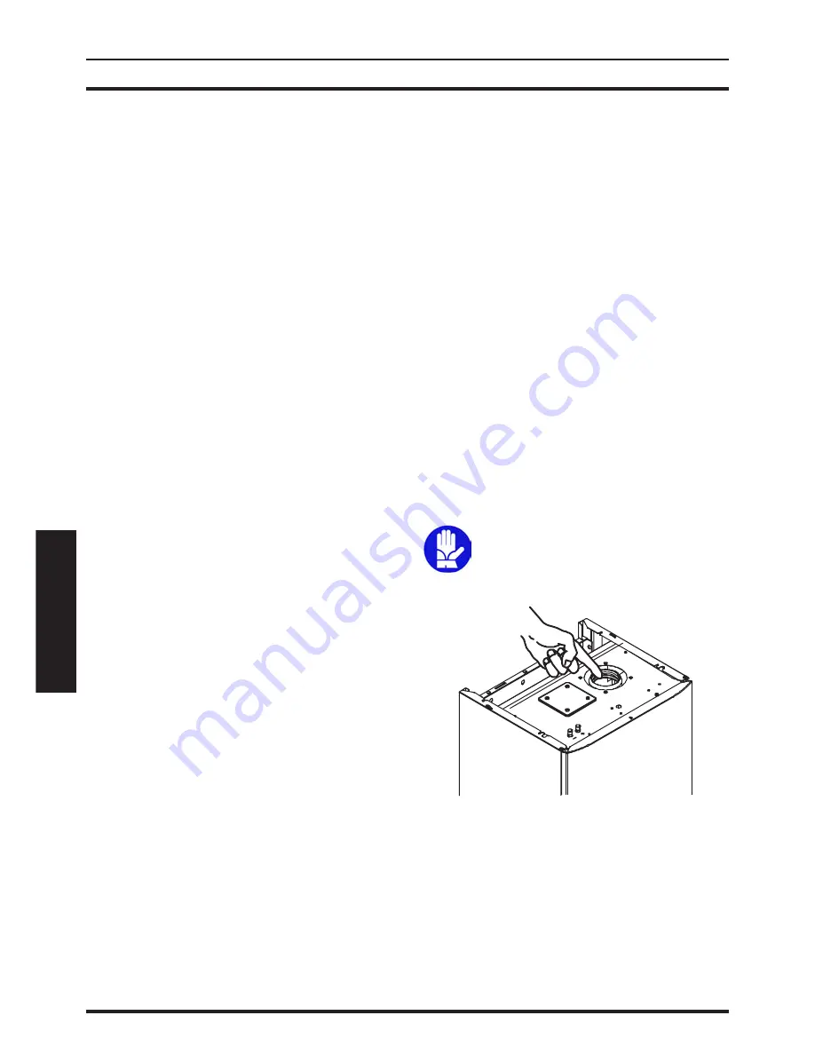
Fill the built in condensate trap
by removing the flue elbow and
pouring a cupful of water into
the flue outlet (Fig. 7.3).
Fig. 7.3
An alternative, to the removal of the flue el-
bow, pour the water through the flue sam-
pling point (Fig. 7.4)
Summary of Contents for Riva Plus HE M296.24SC
Page 56: ...56 NOTES...
Page 57: ...57 NOTES...

