- 13 -
CoNdENSiNG HEAT ExCHANGER
6
CoNdENSiNG HEAT ExCHANGER
6.1 function
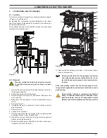
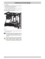
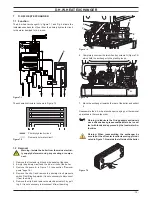
The return water flows through the condensing heat exchanger A
in Figure 6.1 and Figure 6.2.
By reducing the combustion products temperature, the latent
heat of the vapour is transferred to the water circuit, allowing an
extra gain of useful heat.
The condensed vapour is then drained through the condensate
trap B and the draining pipe C.
figure 6.1
A
b
C
6.2 Removal
Warning: isolate the boiler from the mains electrici-
ty supply before removing any covering or compo-
nent.
1 Remove the case panels and the sealed chamber lid (section
"Body panels" page 5).
2 Empty the primary circuit of the boiler.
3 Remove the fan D in Figure 6.2 (see section "Removal of the
Fan" page 39).
4 Disconnect the connectors of the flue temperature probe
NTC E.
5 Remove the clip F.
6 Completely loosen the connection G and slightly move the
pipe H upwards.
7 Remove the clip I.
8 Loosen the connection J.
9 Free the pipe K from the connection of the condensing heat
exchanger; lift and rotate it towards right.
10 Using pliers, remove the spring L moving it to wards right and
disconnect the rubber pipe M.
11 Rotate the exchanger as indicated by the arrow and remove
it towards the front of the boiler.
figure 6.2
A
E
f
H
i
d
l
M
G
K
J
12 Reassemble the exchanger carrying out the removal opera-
tions in reverse order.
Warning: to lubricate the o-ring gaskets exclusively
use a silicone base grease compatible to be in con-
tact with foods and approved by the local water Au-
thorities.
After reassembling ensure that the fan-exchanger and ex-
changer-elbow gaskets are correctly mounted and ensure a
good sealing.
Warning: After cleaning or replacement as detailed
above, if it deemed necessary to undertake a com-
bustion analysis, refer to the appropriate chapter
Maintenance of the installation instructions manual.

