background image

- 40 -

iGNiTioN ANd dETECTioN ElECTRodES

18  iGNiTioN ANd dETECTioN ElECTRodES

18.1 function

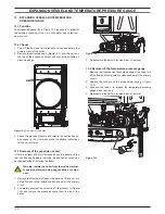
Three electrodes are fitted on the burner. Two of them are the 
ignition electrodes and are fitted near the front part of the burner. 
The ignition sparks take place between their metallic edges over 
the central ramp of the burner during the ignition sequence.
The third electrode is the detection electrode and it detects the 
presence of the flame.

figure 18.1

Ignition

Detection

Male

Female

18.2 Checks


Check the position of the electrode edges

Warning: isolate the boiler from the mains electrici-

ty supply before removing any covering or compo-

nent.

1  Remove all the case panels, the sealed chamber lid and the 

combustion chamber lid.

2  Check for the correct distance between the metallic edges of 

the ignition electrodes (see Figure 18.2).

figure 18.2

Ignition

4 mm

3  Check the integrity of the detection electrode and ensure 

that its metallic edge is correctly placed over the ramp of the 
burner.


Check the connection wires.

Warning: isolate the boiler from the mains electrici-

ty supply before removing any covering or compo-

nent.

1  Remove all the case panels, the sealed chamber lid and the 

combustion chamber lid.

2  Check for the integrity of the insulation of wires which con-

nect the electrodes to the ignition device.

18.3 Removal

Warning: isolate the boiler from the mains electrici-

ty supply before removing any covering or compo-

nent.

1  Remove all the case panels, the sealed chamber lid and the 

combustion chamber lid.

2  Disconnect the electrode wires from the full sequence ignition 

device.

3  Remove the plate E (see Figure 5.3 on page 12).
4  Remove the burner by unscrewing the four screws placed at 

the right and left sides of the burner.

5  Unscrew the screws A (Figure 18.3) which hold the elec-

trodes to the burner.

figure 18.3

A

6  Extract the electrodes from the burner.
7  Assemble the electrodes carrying out the removal operation 

in reverse order.

  Refer to Figure 18.1 in order to recognise the electrodes and 

to correctly connect the wiring.

Note: the metallic edge of the detection electrode is longer 

than the one of the ignition electrodes.

Warning: After cleaning or replacement as detailed 

above, if it deemed necessary to undertake a com-

bustion analysis, refer to the appropriate chapter 

Maintenance of the installation instructions manual.

Summary of Contents for Riva Plus HE M296.24SM/C

Page 1: ...Combi boiler Leave this manual adjacent to the gas meter Warning Service repairs must be carried out only by a qualified Gas Safety Registered Engineer who will be responsible for the current Regulati...

Page 2: ......

Page 3: ...tronic control p c b 25 10 12 Thermal control in the mode 27 10 13 Thermal control in the mode 27 10 14 Ignition and control sequence 28 11 Modulating gas valve 29 11 1 Function 29 11 2 Nomenclature o...

Page 4: ...probe Expansion vessel Detection electrode valve Condensing Divertervalve Flue temperature probe NTC Primarycircuit Combustion chamber over heat heat exchanger Condensate trap pressureswitch Airpress...

Page 5: ...ove screws A Figure 2 2 lift the panel and remove it Figure 2 2 A To remove the side panels loosen the screws B and C Figure 2 3 bring the base of the panels away from the boiler and lift them freeing...

Page 6: ...remove the lid of the sealed chamber For this pur pose remove the front and side panels of the case remove the screws G as indicated in Figure 2 6 and remove the lid 2 5 Emptying the primary circuit 1...

Page 7: ...e way diverter valve Pump M Primary circuit pressure switch Air pressure sensor D h w flowmeter C h temperature probe NTC Modulating gas valve Safety thermostat Flue probe NTC D h w temperature probe...

Page 8: ...J1 1 L Transformer ACTIVE CIRCUIT INACTIVE CIRCUIT L LINE N NEUTRAL N Electronic control p c b low voltage section J1 2 J3 3 J3 5 J3 4 J3 2 J3 1 J2 4 J2 5 Three way diverter valve Pump Full sequence...

Page 9: ...ages with burner on during c h or d h w operation only during c h operation only during d h w operation Supply network 230 230 0 230 230 0 Pump 3 way 230 Modulating Gas valve diverter valve Safety the...

Page 10: ...push button the boiler turns on and operates cor rectly J J 6 J J J By pressing the reset push button the boiler starts the ignition cycle The burner doesn t light on the igni tion sparks continue an...

Page 11: ...on on c h J J J J Water leaks from the safety valve when the boiler is off J J J Note Useful information can be obtained also from the optical indication given by the appliance oper ation lights see s...

Page 12: ...y to disconnect it from the wiring Figure 5 3 F H N P J I K M E O G C B C D L 8 Loosen the connection L and move the pipe M downwards freeing it from the connection of the primary het exchanger 9 Remo...

Page 13: ...Completely loosen the connection G and slightly move the pipe H upwards 7 Remove the clip I 8 Loosen the connection J 9 Free the pipe K from the connection of the condensing heat exchanger lift and r...

Page 14: ...changer lid clean with a brush or non metallic bristle brush Figure 6 3 N O L M 4 Reassemble the exchanger carrying out the removal opera tions in reverse order Warning to lubricate the O ring gaskets...

Page 15: ...nd remove the primary circuit pressure switch D by lifting it upwards It is not necessary to disconnect it from the wiring 5 Remove the clip E and remove the electric actuator F by pull ing it It is n...

Page 16: ...il 2 Figure 8 2 Check the absence of starting defects With the boiler off remove the front case panel Remove the air release plug from the pump Start the boiler and with a screwdriver turn the rotor i...

Page 17: ...d the return water group 8 4 Removal electrical capacitor Warning isolate the boiler from the mains electrici ty supply before removing any covering or compo nent 1 Remove the front and right hand sid...

Page 18: ...on of the actuator B brass spindle when the boiler operates in c h mode In both figures the relationship between the position of the actua tor and the resistance of the motor windings the motor must b...

Page 19: ...way diverter is correctly oriented by matching the reference G with the notch of the water group Figure 9 5 9 5 Removal of the diverter group 1 Remove the front and both side case panels 2 Empty the p...

Page 20: ...d supplies the fan and checks its functioning by means of the signal coming from the air pressure sensor The Electronic control ignition p c b has a safety function and any incorrect interventions or...

Page 21: ...able elements 10 and 11 in Figure 10 2 of the electronic control p c b I f the power requested is lower than 40 of the maximum power output then control is achieved by switching ON the burner at minim...

Page 22: ...d their meaning Normally operating boiler see the previous table for details C h operation D h w operation Frost protect operation D h w operation Excessive temperature on primary circuit Faulty c h t...

Page 23: ...t button D pressed for more than 5 seconds The lamps F will flash a number of times corresponding to the setting Figure 10 11 once for M296 24SM C and M296 28SM C Figure 10 11 1 4 7 M296 24SM C M296 2...

Page 24: ...the knob B on a position corresponding to an ade quate ignition pressure Refer to the value indicated in the tables of the User Installa tion manual Technical information section Gas pressures at the...

Page 25: ...a fuse has blown replace it with one that has the same charac teristics after having identified the reason for failure Lock sequence Start the boiler until the burner is ignited With the burner firing...

Page 26: ...ascia making sure of the contact between the boiler reset button B and the tab C Figure 10 24 Figure 10 24 A A B C Attention After installing the Electronic control ignition p c b 10 Make sure the c h...

Page 27: ...the circulator Operates motorised valve Supplies the ignition device NO Circulator off Operates motorised valve Ignition device off YES YES See functioning with the function control in the mode sec 10...

Page 28: ...opens gas valve beginning of ignition period flame presence end of ignition period NO NO YES closes gas valve stops fan interrupts ignition discharges memorizes lock turns on lock out light YES reset...

Page 29: ...ressure adjustment 3 Modulation operator s electric connectors 4 On off operators electric connector 5 On off operators 6 Gas valve inlet pressure test point 7 Gas valve outlet pressure test point 8 M...

Page 30: ...Check the on off operators coils 1 Remove the front panel of the case 2 Disconnect the electrical connector E Figure 11 5 3 Measure the electrical resistance between the connector pins of the on off...

Page 31: ...e electric resistance between the contacts C and N O of the switch 1 Measure the electrical resistance between the tabs marked C and N O Figure 12 2 The contact must close resistance zero with c h pre...

Page 32: ...above the boiler and the rear exit flue can be easily removed the expansion vessel can be changed without removing the boiler Warning isolate the boiler from the mains electrici ty supply before remo...

Page 33: ...ore removing any covering or compo nent Figure 14 3 B C D E 1 Remove the front panel of the case 2 Disconnect the connectors B and remove the sensor holder C Figure 14 3 3 Remove the sensor 14 4 Check...

Page 34: ...1 Figure 14 5 4 Reassemble the parts following the removing sequence in reverse order 14 6 Flow limiter The M296 24SM C model is factory fitted with a 10 litres min flow limiter white To install the f...

Page 35: ...5 2 Checks Sensor operation Warning isolate the boiler from the mains electrici ty supply before removing any covering or compo nent Disconnect the cable from the Temperature probe Measure the tempera...

Page 36: ...ature probe B Figure 15 4 5 Reassemble the d h w temperature probe carrying out the removal operations in reverse order Warning to lubricate the O ring gaskets exclusively use a silicone base grease c...

Page 37: ...removing any covering or compo nent 1 Remove all the case panels 2 Empty the primary circuit of the boiler 3 Remove the locking plate B and pull up the by pass valve A Figure 16 3 Figure 16 2 A B 4 R...

Page 38: ...cal resistance of the motor that has to be about 43 M296 24SM C 25 M296 28SM C at ambient temperature Figure 17 2 A C B Check of the Air pressure sensor operation This test must be carried out with th...

Page 39: ...ement as detailed above if it deemed necessary to undertake a com bustion analysis refer to the appropriate chapter Maintenance of the installation instructions manual 17 4 Removal of the Air pressure...

Page 40: ...supply before removing any covering or compo nent 1 Remove all the case panels the sealed chamber lid and the combustion chamber lid 2 Check for the integrity of the insulation of wires which con nect...

Page 41: ...safety thermostat and no overheat intervention should occur Warning isolate the boiler from the mains electrici ty supply before removing any covering or compo nent Electrical function 1 Remove all th...

Page 42: ...lue pipes are integral parts of the boiler If not the electronic control p c b attempts to light the burner and at the end locks the boiler and lights the lock out signal lamp Figure 20 3 A B 20 2 Che...

Page 43: ...trap and reaching the condensing heat exchanger When the condensate reaches the lower part of the exchanger obstructs the exhaust gas flow and the boiler stops no signal from the air pressure sensor...

Page 44: ...96 24SM C 1 BI1326 107 E83 181 Combustion chamber rear panel mod M296 28SM C 1 BI1326 108 11 H74 591 Combustion chamber front panel mod M296 24SM C 1 BI1536 110 H74 592 Combustion chamber front panel...

Page 45: ...45 Short spare parts list 1 2 6 4 5 7 3 8 14 12 18 20 21 23 25 26 13 15 24 16 17 9 10 11 9 19 27 22 Figure 22 1...

Page 46: ...46 NOTE...

Page 47: ......

Page 48: ...1796215495 17962 1549 5 0312 48A4 UK Biasi UK Ltd Commercial Road Leamore Enterprise Park WALSALL WS2 7NQ Sales Tel 01922 714600 Tech Service Tel 01922 714636 www biasi co uk 16 01 2012 N...

Reviews: