- 30 -
Fan and air pressure sensor
14 fan and air pressure sensOr
14 .1 function
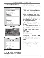
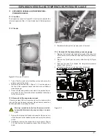
The function of the Fan A (Figure 14.1 and Figure 14.2) is to
force the products of combustion through the condensing heat
exchanger to the outside air via the flue system.
The Fan is supplied by the full sequence ignition device at the
beginning of the ignition cycle.
Its correct functioning is controlled by means of an Air pressure
sensor B (Figure 14.1 and Figure 14.2) .
figure 14 .1
a
b
14 .2 checks
Check of the fan
warning: isolate the boiler from the mains electrici-
ty supply before removing any covering or compo-
nent .
1 Remove all the case panels and the sealed chamber lid.
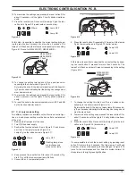
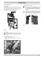
2 Disconnect the connectors C (Figure 14.2) and measure the
electrical resistance of the motor that has to be about:
43 Ω - M296.24SR/C
25 Ω - M296.28SR/C
(at ambient temperature).
figure 14 .2
a
c
b
Check of the Air pressure sensor operation
this test must be carried out with the sealed chamber
closed .
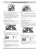
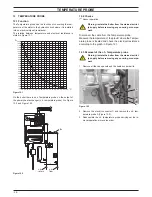
1 Remove the caps of the pressure test points located on the
top of the boiler and connect a differential pressure gauge
(Figure 14.3).
2 Switch on the boiler.
figure 14 .3
3 Run the boiler at minimum by disconnecting the gas valve
modulation operator.
4 Compare the value on the gauge with the following:
75 Pa (0,75 mbar) - M296.24SR/C
92 Pa (0,92 mbar) - M296.28SR/C
5 Run the boiler at maximum (connect the modulation opera-
tor).
6 Compare the value on the gauge with the following:
125 Pa (1,25 mbar) - M296.24SR/C
155 Pa (1,55 mbar) - M296.28SR/C
7 With values less than:
64 Pa (0,64 mbar) - M296.24SR/C
82 Pa (0,82 mbar) - M296.28SR/C
The ignition is not allowed and appropriate fault indication is
given (see section "Operation lights" page 17).

