17
8
Three way diverter valve
8.1
Function
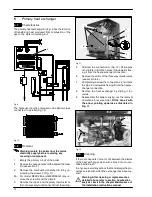
The diverter valve
A
(Fig. 20) has the function of modify-
ing the hydraulic circuit of the boiler by means of an
electric command given by the electronic control p.c.b.
in order to send the water that exits the primary heat ex-
changer towards the c.h. system or towards the d.h.w.
heat exchanger.
A
Fig. 20
8.2
Checks
n
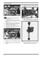
Check the electrical continuity
Fig. 21 indicates the relationship between the electric
command coming from the electronic control p.c.b.
and the position of the actuator
B
(brass spindle) when
the boiler operates in
d.h.w. mode.
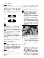
Fig. 22 indicates the relationship between the electric
command coming from the electronic control p.c.b.
and the position of the actuator
B
(brass spindle) when
the boiler operates in
c.h. mode.
In both figures the relationship between the position of
the actuator and the resistance of the motor windings
(the motor must be disconnected from the wiring) is
also given.
B
bn = brown
bu = blue
bk = black
0
V
23
0
V
Spindle B
not visible
Open circuit
9,4 Kohm
bk
bn
bu
3
1
2
Fig. 21 --- D.h.w. mode
B
bn = brown
bu = blue
bk = black
23
0
V
0
V
Spindle B
visible
Open circuit
9,4 Kohm
bk
bn
bu
3
1
2
Fig. 22 --- C.h. mode
8.3
Removal of the electric actuator
Warning: isolate the boiler from the mains
electricity supply before removing any
covering or component.
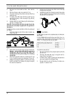
1
Remove the front case panel.
2
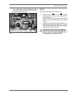
Disconnect the connectors
C
(Fig. 23).
3
Remove the fixing spring
D
and remove the
actuator
E
.
Reassemble the actuator carrying out the re-
moval operations in the reverse order.
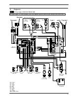
When reassembling the actuator, refer to Fig. 21
or to the wiring diagram in section 3.1 for the cor-
rect wiring connection.
Summary of Contents for RIVA PLUS M90S.24S
Page 2: ......


