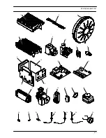
Fan
36
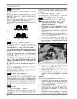
Fig. 70
3
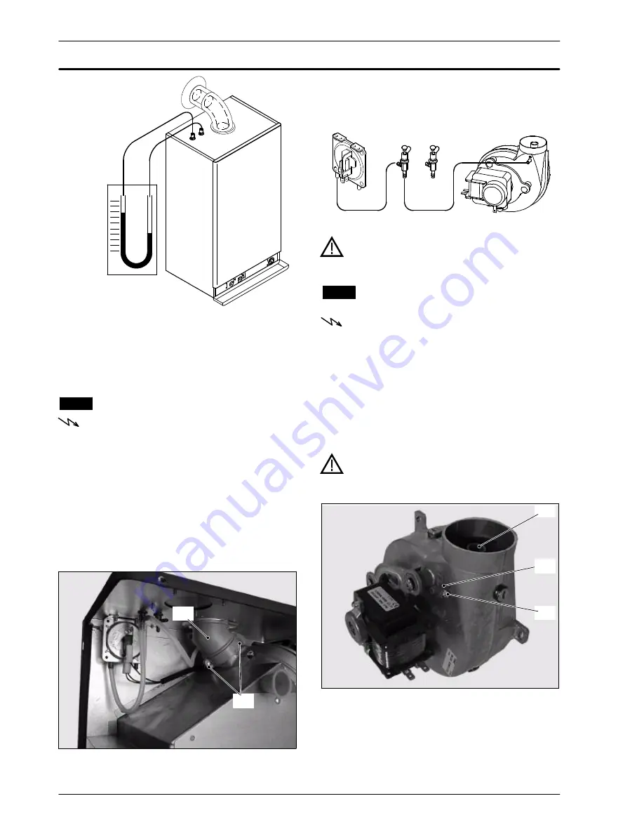
Compare the value on the gauge with the follow-
ing minimum values:
90 Pa (0,9 mbar) --- M90D.24S, M90D.24SR
100 Pa (1,0 mbar) --- M90D.28S, M90D.28SR
17.3
Removal of the Fan
Warning: isolate the boiler from the mains
electricity supply before removing any
covering or component.
1
Remove all the case panels, the sealed chamber
lid and the combustion chamber lid.
2
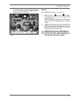
Disconnect the connectors
B
and the earth con-
nection
C
(Fig. 67).
3
Disconnect the pipe which connect the venturi
device to the Air pressure switch.
4
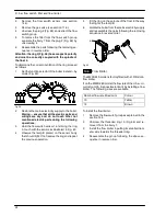
Unscrew the screws
D
and remove the clamp
E
(Fig. 71).
D
E
Fig. 71
5
Remove the three screws
F
(Fig. 67) securing the
Fan to the flue hood and remove the fan.
6
Assemble the fan carrying out the removal oper-
ations in reverse sequence.
Warning: to correctly connect the venturi device to
the Air pressure switch, refer to Fig. 72.
---
+
Fig. 72
Warning: After cleaning or replacement as
detailed above refer to section
Combustion
analysis check
in the chapter
Maintenance
of
the installation instructions manual.
17.4
Inspection and removal of the venturi
device
Warning: isolate the boiler from the mains
electricity supply before removing any
covering or component.
1
Remove the fan (section 17.3).
2
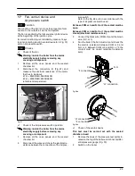
Remove the venturi device by unscrewing the
screw
G
.
3
Inspect the venturi device
A
and the connection
pipe
H
. Ensure they are clean.
4
Re---assemble the parts in reverse order of re-
moval.
Warning: After cleaning or replacement as
detailed above refer to section
Combustion
analysis check
in the chapter
Maintenance
of
the installation instructions manual.
A
G
H
Fig. 73
Summary of Contents for RIVA PLUS M90S.24S
Page 2: ......

