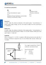
User’s Manual UPSI-B-2440
Bicker Elektronik GmbH
||
Tel. +49 (0)906 70595-0
||
www.bicker.de
||
info@bicker.de
22
E
n
g
lis
h
3 Functional Description
In case of a mains voltage failure the DC UPS UPSI-B-2440 supplies the connected
consumer load with DC voltage from the connected battery pack. Via LED display the
status is visualised. Signals can be informed to a connected PC via interface.
3.1 Mains Mode
In mains mode a voltage source at the input line supplies 24 V DC. This voltage minus
0.4 V DC is provided directly at the consumer load (e. g. PC). The connected battery
pack is charged by the UPSI-B-2440. The LED is green and the interface signalises
“Power ok“. App. every 10 minutes a battery test is carried out. In case of a defect
battery or if the battery pack is not connected, the LED flashes red/green.
3.2 Battery Mode
If the supply voltage drops below the switch-over threshold at the input of the
DC UPS UPSI-B-2440, the UPSI-B-2440 takes over supplying the connected consu-
mer loads. The LED is orange and the interface signalises “Power Fail“. When the
capacitance of the connected battery pack decreases (battery voltage dropping to
<21 V), the interface signalises “Battery Low“. The LED flashes red/orange. The DC UPS
UPSI-B-2440 can be switched off by an impulse at the “Shutdown“ input.
AC
DC
DC UPS
UPSI-B-2440
Consumer
load (PC)
Interface
Battery
pack
BP-2450C
Source:
e. g. AC/DC power supply
50 A


