background image

UPSI-1208DPx

Revision 1-5

29

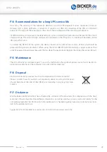
F14  Recommendations for a long UPS service life

Over time, the capacity of the Supercaps decreases and the ESR (equivalent series resistance) increases. 
However, EOL is often defined as a reduction in capacity to 70 % and a doubling of the ESR. An important 
aspect for the aging of the Supercaps is the end-of-charge voltage and the operating temperature. 

LiFePO4 batteries also age over time depending on cycles, operating temperature and the level of the end-of-
charge voltage. The end-of-charge voltages are optimized so that they are at an optimium between service 
life and performance.

To extend the lifetime of the system, the device should not be placed near sources of heat and should be  
placed within good air-circulation. When using the UPSI-1208DP3 (LiFePO4 battery), a larger capacity than 
actually required should always be used. The less deep the packs are discharged, the longer the service life lasts.

F15 Maintenance

The UPS contains no serviceable parts. In case of a malfunction the upstream power source has to be discon-
nected and cables have to be removed. Use a dry cloth for cleaning!

F16 Disposal

Electric and electronic devices must not be disposed with domestic waste! 
Please consider to each country’s own regulation about recycling and disposal 
of used batteries at the end of their lifetime or resending to any recycling orga-
nization.

F17 Disclaimer

We, the Bicker Elektronik GmbH, have checked the contents of this document for compliance with the hard-
ware and software described. Nevertheless, deviations can not be ruled out, so we assume no liability for the 
complete agreement. The information in this publication is checked regularly, necessary corrections are inclu-
ded in the updated versions. 

Suggestions for improvement as well as tips and criticism are always welcome.

Summary of Contents for UPSI-1208DP Series

Page 1: ...User Manual UPSI 1208DPx Bicker Elektronik GmbH Ludwig Auer Stra e 23 86609 Donauw rth Germany English UPS SYSTEM DIN RAIL...

Page 2: ...ded use more detailed specified Chapter C1 Environmental conditions more detailed specified Indoor Outdoor Page 2 Warning Read User Manual at explanation Legend of used symbols supplemented 25 11 2020...

Page 3: ...UPSI 1208DPx Revision 1 5 3...

Page 4: ...erating Storage Transport DP2 20 65 C DP2 30 65 C DP3 20 55 C DP3 30 55 C recommended state of charge 80 Operating altitude 4000 m Max permitted humidity 95 at 25 C no dew Dimensions W H D 63 x 120 x...

Page 5: ...attery capacitance load and temperature At very high or low temperatures a reduction of backup time occurs Unless otherwise specified the values apply to measurements at 25 C 10 15 20 25 30 35 40 45 5...

Page 6: ...n advice 19 F2 Convection and installation position 19 F3 Description of connectors 21 F4 Dimensioning the upstream power supply 22 F5 Connecting diagram 23 F6 Initial operation 24 F7 Overview connect...

Page 7: ...mode automatically The input voltage is passed through to the output and the integrated energy storage device is charged simultaneously The charging current depends dynamically on the load current at...

Page 8: ...er and fire hazards and can then be used indoors and outdoors It is primary built for being mounted on a DIN Rail and is intended for professional use in applications such as industrial control commun...

Page 9: ...put obviously damaged devices into operation e g dents burn marks rough contamination 9 Keep ventilation openings clear 10 Device must not be dropped 11 All parts of the device and accessories must n...

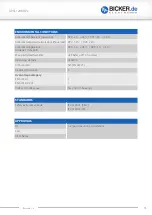
Page 10: ...strength max 18 VDC Fixed connect threshold Undervoltage Voltage drop Input Output 11 5 VDC 0 6 VDC max depending on load Current consumption IN UN IOUT IN ICHARGE 0 IMAX UN IOUT ISTAT BOOST ICHARGE...

Page 11: ...OST UN IOUT IDYN BOOST ICHARGE 0 96 W 99 W n a Short circuit proof Yes No load proof Yes Overcurrent shutdown 8 5 9 5A for max 3ms 9 5A for max 5ms OUTPUT DATA UPSI 1208DP2 UPSI 1208DP3 BATTERY MODE U...

Page 12: ...0835 Charging method CC CV CP Nominal voltage UN 8 3 V End of charge voltage 8 3 V Charging current 16 A max Undervoltage protection 4 5 V Battery technology EDLC Nominal capacity 5 73 kJ 3 88 kJ usef...

Page 13: ...A RELAY Connection labeling RL Switch contact potential free Relay Status configurable Power Fail Alarm Switching voltage 24 VDC 125 VAC Current carrying capacity 1 A DC 0 5 A AC State signal assignme...

Page 14: ...ail mounting EN 60715 Housing version Aluminium Dimension W H D 63 mm 120 mm 100 mm 0 5 mm without front connectors and DIN Rail mounting bracket DATA INTERFACE RS232 Interface designation RS232 Numbe...

Page 15: ...erature storage transport DP2 30 65 C DP3 30 55 C Max permitted humidity 95 at 25 C no dew Operating altitude 4000 m Climate class 3k3 EN 60721 Degree of pollution 2 Overvoltage category EN 61010 1 EN...

Page 16: ...mment 4 kV 8 kV Criterion B Electromagnetic HF field EN 61000 4 3 Frequency range Test field strength Frequency range Test field strength Comment 80 MHz 1 GHz 10 V m 1 4 GHz 2 GHz 3 V m Criterion A Fa...

Page 17: ...avior that is corrected by the device itself EMISSION ACCORDING TO EN 55016 2 3 DOMESTIC Basic standard CE Fulfilled requirements according to EN 55016 2 3 CE Domestic Conducted emission from the powe...

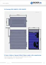
Page 18: ...1208DP2 UPSI 1208DP3 63mm 120mm 9mm 100mm 44mm Tolerance 0 5 mm E Name Address Support E Mail Phone number of the manufacturer Bicker Elektronik GmbH Ludwig Auer Stra e 23 86609 Donauw rth Germany E...

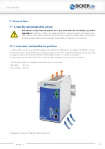
Page 19: ...orrect polarity Before commissioning check all the connections for correctness F2 Convection and installation position For these DIN rail versions vertical mounting on a horizontal rail DIN rails acco...

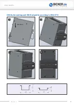
Page 20: ...UPSI 1208DPx Revision 1 5 20 DIN Rail mounting and DIN Rail profile according to EN 60715 2 3 4 1 Press down...

Page 21: ...ax 2 RXD 3 TXD 4 DTR 5 GND 6 DSR 7 NC 8 NC 9 NC RELAY CONNECTION RL The function of the relay connection is configurable via software When closing the relay the resistor value between both contacts is...

Page 22: ...pplied from a SELV or PELV power supply In order to operate the UPS devices with complete functionality the upstream power supply has to provide at least 12V 10A and use no constant current function I...

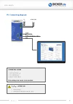
Page 23: ...ndividual use D Sub 9 RELAY F5 Connecting diagram VIN VOUT ATTENTION 1 Note polarity 2 AWG18 wire should be used 1 mm2 CONNECTING ORDER 1 APPLICATION VOUT 2 DC SOURCE VIN 3 RELAY USB RS232 Dismantling...

Page 24: ...After that the charging of the energy storage starts The applied voltage at the input of the UPS is passed through to the output reduced by a current dependent voltage drop VOUT VIN 0 6 V at maximum c...

Page 25: ...g commissioning If the device operates in battery mode and the input terminals are connected with reverse polarity no reverse polarity protection is given Overload If the load current at the output is...

Page 26: ...charge protection With supercapacitors in particular an additional switch off threshold can take effect if the discharge current of the energy storage device is too high 15 A This can occur at very hi...

Page 27: ...LED is off briefly pause 2s Status Reboot Output is deactivated and time until reboot runs Reboot phase UPS FAILURES Quick flashing without pause Status UPS failure Output current too low UPS is deact...

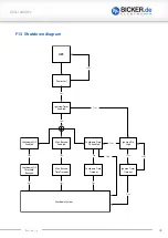
Page 28: ...ail True Shutdown SOC Threshold Reached Max Backup Time Timeout Shutdown Timer Timeout Shutdown SOC Enabled Max Backup Enabled Shutdown Timer OS Enabled Ignition Timer Timeout Ignition Pin High True F...

Page 29: ...acity than actually required should always be used The less deep the packs are discharged the longer the service life lasts F15 Maintenance The UPS contains no serviceable parts In case of a malfuncti...

Page 30: ...a not intended Power Fail could be caused With maximum load the voltage at the input of the device must not undercut 11 5V Even after the upstream supply has been disconnected the device continues to...

Page 31: ...ions Windows is a registered trademark of the Microsoft Corp Status as at 01 04 2021 Revision 1 5 Bicker Elektronik GmbH Ludwig Auer Stra e 23 86609 Donauw rth Germany Tel 49 0 906 70595 0 Fax 49 0 90...

Reviews: