HR M
ANUAL
I
NSTALLATION
Manual version 3.0 (10-10-2017)
en-15
en
• In exceptional situations, water may run out of the unit.
Make sure that this cannot cause any damage or danger-
ous situations.
•
For models with heating:
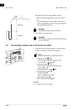
The distance between the ceiling
and the top of the unit must be more than 25 mm.
See also:
2.2.2 Hanging the unit up
This manual explains how to suspend the unit for each mod-
ule. Depending on the situation, a different sequence of sus-
pending the units may be selected.
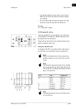
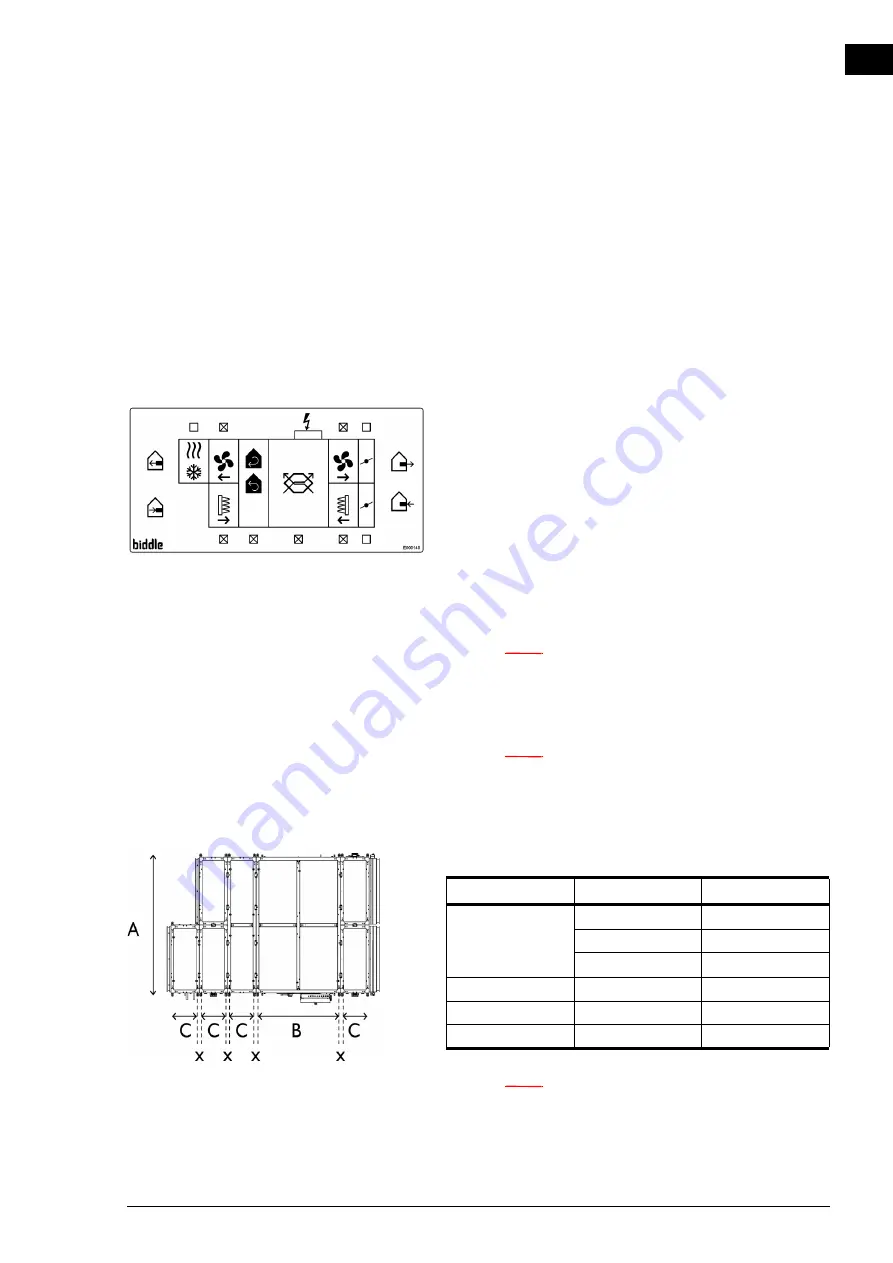
Consult the overview sticker for the module positions in the
specific composition of your unit.
Fixing the threaded rods
Fix threaded rods M10 in accordance with the dimensions in
the table. Make sure the threaded rods are perpendicular.
Note:
n
Only fix the threaded rods for the modules in the
specific composition of your unit. See the overview
sticker.
Note:
n
The illustration shows the unit from above, whereby
the air exchange with the interior takes place on the
left side and the air exchange with the exterior takes
place on the right side.
Note:
n
The threaded rods must be secured, otherwise the
unit may fall down.
SIZE
TYPE
DIMENSIONS
A
HR 25
1558 mm
HR 35
2158 mm
HR 45
2758 mm
B
all models
1450 mm
C
all models
450 mm
x
all models
54 mm


