background image

I

NSTALLATION

H

EAT


RECOVERY


UNIT

en-20

en

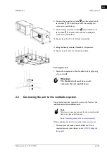
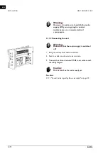
Pay attention to the following installation criteria:

- Make sure the drainage pipe has a drop of at least 1 in 

50.

- Fit the drainage pipe with a trap with dimensions as 

shown in the illustration. Fill this with water before the 
unit is used for the first time.

Caution:

c

The trap must always be filled with water.

2. Cap off other connection points.

Caution:

c

If the connection points are not shut off, water may 
run out of the unit.
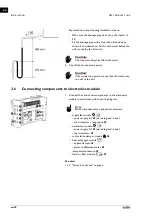
2.6

Connecting components to electronics module

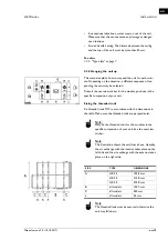
1. Connect the various unit components to the electronics 

module in accordance with the wiring diagram:

Note:

n

Some components are optional (accessories).

- supply fan module 

:

- power supply: X1 

1

 (via cable gland in box)

- control input valve: 

2

- extract fan module 

:

- power supply: X1 

3

 (via cable gland in box)

- control system: 

4

- recirculation damper module  : 

5

- heat  exchanger  module 

:

- by-pass damper: 

6

- pressure difference meter: 

7

-temperature sensors: 

8

- fresh air filter module 

9

See also: 

1.3.3 "Symbols on the unit" on page 6

Summary of Contents for HR 25

Page 1: ...a Manual Heat recovery unit Model HR 25 35 45 Version 3 0 Original Manual English...

Page 2: ...ol panel accessory 21 2 9 Installing sensors for control optional 23 2 10 Installing external controls 23 2 11 Connecting the unit to the mains supply 25 2 12 Switching on and checking operation 27 3...

Page 3: ...nance 59 7 Service 60 7 1 Cleaning the plate heat exchangers 60 7 2 Removing the control circuit board 62 7 3 Connecting the control circuit board 62 7 4 Fuses 63 7 5 Setting the unit code 63 7 6 Rese...

Page 4: ...used in the manual Note n Refers to an important section in the text Caution c If you do not carry out the procedure or action correctly you may cause damage to the unit Follow the instructions preci...

Page 5: ...ut additional heating Other versions and intended use Warning w Applications other than those described above are deemed to be usage other than for the intended purpose Biddle is not liable for damage...

Page 6: ...s are equipped with stickers and symbols These symbols provide information on function airflow components TYPE CODE ELE MENT DESIGNATION MEANING product series HR general designa tion for the series c...

Page 7: ...pe plate filter heating cooling AIRFLOW SYMBOL supply air extract air exhaust air fresh air FUNCTION SYMBOL DESIGNATION MEANING Type complete type code of the unit No serial number production week and...

Page 8: ...area velocity typical max 1 9 2 6 m s 1 5 2 4 m s Nominal external pressure max ps ext 200 Pa 300 Pq Internal pressure drop ventilation max ps int 350 Pa 440 Pa Internal pressure drop additional max p...

Page 9: ...ximum sound power level in ducts Ambient conditions Temperature 5 C to 40 C Relative air humidity 20 95 not condensing Power supply voltage see type plate Power see type plate SOUND POWER LEVEL LW RE...

Page 10: ...page 7 1 3 7 CE declaration The unit is compliant with the applicable CE standards The complete CE Declaration of Conformity can be found at www biddle info 1 3 8 Modifications and changes Without th...

Page 11: ...ement 7 depending on the type of unit Electronics module 8 Fastening material for linking the modules to each other 1 4 2 Accessories Flexible cuffs attached to modules 0 Air dampers to fresh air atta...

Page 12: ...In exceptional situations water may run out of the unit Therefore do not place anything under the unit that could be damaged as a result 1 5 2 Safety issues relating to installation mainte nance and s...

Page 13: ...ains supply switch off the isolation switch 4 If you are going to carry out maintenance or repairs on electrical components switch the mains supply group off 5 For water heated models shut off the cen...

Page 14: ...ure that all components are present Notify supplier of any missing parts immediately See also 1 4 Components and accessories on page 11 2 2 Hanging the unit up 2 2 1 Determining the location of the un...

Page 15: ...ew sticker for the module positions in the specific composition of your unit Fixing the threaded rods Fix threaded rods M10 in accordance with the dimensions in the table Make sure the threaded rods a...

Page 16: ...s and rings 2 for damping stay in the right place Caution c Make sure that the module is hanging level in both directions 4 To each threaded rod apply a lock nut 3 5 Move the recirculation damper modu...

Page 17: ...the heating module Securing the unit 1 Secure the suspension to the threaded rods by tightening all lock nuts 3 Warning w The threaded rods must be secured otherwise the unit may fall down 2 3 Connec...

Page 18: ...ting and heat recovery sys tem 2 4 1 Connecting the water side control accessory Only for models with water heating cooling module The heating cooling module can be fitted with a water side control to...

Page 19: ...Vent the heat exchangers 3 Check the connections for leakage 2 5 Installing condensate drain The cooling of the air can cause condensation The unit is fit ted with one or more drain trays to catch co...

Page 20: ...n points are not shut off water may run out of the unit 2 6 Connecting components to electronics module 1 Connect the various unit components to the electronics module in accordance with the wiring di...

Page 21: ...ttach the control panel to the electronics mod ule to the wall or to a standard junction box Cabling Note n Take the following into account otherwise errors may occur The length of the control cable b...

Page 22: ...ol panel out of the wall holder 3 Connect the control cable to terminal X397 Caution c Ensure that the wall behind the wall holder is even 4 Screw the wall holder onto the electronics module the junct...

Page 23: ...level in the room must be optimal at least once per week so that the sensor can maintain a good calibration level If this situation does not occur naturally you can make it happen by for example havin...

Page 24: ...ecial mode See 60 Function of inputs This function can be activated by the building management sys tem register address 435 or by an external sensor If an external sensor is used 1 Place a smoke detec...

Page 25: ...X3 1 of the electronics module in accordance with the wiring diagram Caution c Keep the cable length to a maximum of 3 metres Note n The positions of the and contacts in the lamp are indicated by 28V...

Page 26: ...onents 2 11 2 Connecting the unit Warning w Make sure that the mains supply is switched off 1 Bring the mains power cable to the unit 2 Feed the cable into the electronics module 3 Connect the cable o...

Page 27: ...ion coupling elements between the modules channel sections correctly connected and in the right positions 2 Check that the trap of the condensate drain is filled with water 3 Check the connections to...

Page 28: ...INSTALLATION HEAT RECOVERY UNIT en 28 en...

Page 29: ...that is being used See type plate Set all and any connected ventilation units to the set ting appropriate to setting 1 low of the HR unit Set the desired flow rate for setting 1 low by adjust ing the...

Page 30: ...al test mode 7 the fan runs but there is no pressure difference because the air damper is closed Opmerking n The opening and closing of the dampers can take a little while MODE FANS SPEED VALVES NO DE...

Page 31: ...alistic values Tfresh Tsupply Tex tract Texhaust 2 12 7 Checking the CO2 sensor accessory If a CO2 sensor is used 1 Check in menu Maintenance Checking HR unit that the sensor is measuring a realistic...

Page 32: ...b touch control panel or conversely only via BMS 3 1 Control panel The b touch control panel is equipped with a touchscreen touch screen with which all the functions can be set Turning the unit ON an...

Page 33: ...FF manually using the con trol panel Touch on off in order to turn the unit ON or OFF If the unit is on the screen will become darker after some time in order to save energy When the screen is touched...

Page 34: ...Biddle recommends selecting the lowest strength at which the desired air quality is achieved 3 2 4 Errors The symbol indicates that there is an error The error mes sage is displayed alongside Touch t...

Page 35: ...ist If the control panel is not operated for some time it returns automatically to the Home screen without saving the changes Lock screen Select Lock screen to prevent unauthorised access The symbol a...

Page 36: ...basis of the usage of the unit if no filter sensor has been installed You can adjust this by setting the maximum lifespan of the filter When the filters are contaminated or when the maximum lifespan...

Page 37: ...for ward Celsius Fahrenheit Choose between a temperature display in degrees Celsius or degrees Fahrenheit Display brightness Set the brightness of the screen to your personal preferences or to the spe...

Page 38: ...ses 20 Access control Pin code Access to the entire control panel or to the menu only can be protected with a four digit PIN code The default PIN code is 0000 Access level The control panel can be saf...

Page 39: ...versions of the unit Note n Leave ventilation control in manual mode 46 Maximum discharge temperature Not applicable to all versions of the unit The controller limits the discharge temperature to a ma...

Page 40: ...tion When the contact is closed air is extracted no air is supplied an alarm signal smoke is sent to the building management sys tem 31 Fire mode When the contact is closed the unit is switched off an...

Page 41: ...r an external ON OFF signal or for an additional tem perature sensor When the timer is in use the ON OFF function of the input on the control panel is deactivated irrespective of this setting 3 7 Main...

Page 42: ...the opening percentage of the valve to 0 2 Press start The fans will start rotating at the highest speed 3 Check whether the discharged air is cold Note n It may take some time before the valve reach...

Page 43: ...control panel searches for connection with the attached units again Use this function when remedying errors and dur ing connection or disconnection of units 3 8 USB The control panel is equipped with...

Page 44: ...Biddle s website See also 7 8 Updating the software Upload logo It is possible to use your own logo or image as background for the display Requirements for the image Windows bitmap Filename logo bmp D...

Page 45: ...hese files can then be ana lysed on a computer The files contain the following data log_func Data concerning the operation of the unit log_error Error report history log_user User settings history log...

Page 46: ...ddresses This paragraph describes frequently used functions and their corresponding register addresses Caution c Do not adjust other register addresses without consulting Biddle Note n It may occur th...

Page 47: ...ng the unit ON and OFF REGISTER ADDRESS DESCRIPTION 400 409 ro User functions Current status 410 419 rw User functions Changes via the b touch control panel 0 permitted default 1 not permitted 420 429...

Page 48: ...elow have been set as follows VALUE OPTION DESCRIPTION 0 manual The unit is operating in various settings can be switched manually 1 automatic The unit automatically operates at the correct fan and da...

Page 49: ...een set as follows 4 1 4 Automatic CO2 control The unit automatically adjusts the fan speed and any recircula tion damper to the CO2 level The CO2 level is supplied by the building management system B...

Page 50: ...have the value 1 default 100 recirculation ventilation REGISTER ADDRESS DESCRIPTION RO RW CONTROL UNIT MINI MUM MAXI MUM DEFAULT 351 62 2 CO2level 1 rw ppm 200 2000 800 352 62 3 CO2level 2 rw ppm 200...

Page 51: ...a recirculation module and in manual control recirculation no heat recovery off 2 ventilation only functional in the case of units with a recirculation module and in manual control ventilation heat re...

Page 52: ...the building manage ment system 31 Fire mode When the contact is closed the unit is switched off any air dampers are closed an alarm signal fire is sent to the building management system 40 Smoke ala...

Page 53: ...11 ventilation auto speed 1 12 ventilation auto speed 2 13 ventilation auto speed 3 14 ventilation auto boost 16 ventilation manual speed 1 17 ventilation manual speed 2 18 ventilation manual speed 3...

Page 54: ...re may be a fault in that case alert the installer See also 2 11 Connecting the unit to the mains supply on page 25 PROBLEM PROBABLE CAUSE WHAT TO DO The unit does not work The unit has not been switc...

Page 55: ...217 ErrorFlags 1 ERROR MESSAGE PROBABLE CAUSE WHAT TO DO The malfunction lamp is lit up The filter is letting insufficient air through due to contamination Check the filter for contamination Clean or...

Page 56: ...rror but no error message is displayed 1 Referring to the preceding sections check whether you can easily resolve the problem 2 Try to resolve the problem using the table below Techni cal expertise is...

Page 57: ...tion register address 337 One or more modules are not prop erly connected Check the connections of the modules Check the operation of the unit See 2 12 5 Checking operation The unit is not circulatin...

Page 58: ...d regularly A dirty filter can cause inefficient operation and a high noise level Remove the filter Warning w Set the isolation switch to 0 1 Open the inspection hatch for the relevant filter 2 Pull t...

Page 59: ...lean enough and undam aged Replace the filters if necessary Check that the heat exchanger or the electrical heating elements are clean Settled dust may cause an unpleasant smell Carefully remove dust...

Page 60: ...use inefficient operation and a high noise level If they are dirty clean the exchangers The exchangers can be extracted in two ways Via the side Via the underside Warning w Set the isolation switch to...

Page 61: ...nger Open the value of the by pass 8 Unscrew the valve motors from the valve 9 When extracting via the underside Push the by pass slightly to the side When extracting via the side Disconnect the cable...

Page 62: ...ontrol circuit board 4 loose and lift it out of the unit 7 3 Connecting the control circuit board Warning w Make sure that the mains supply is switched off 1 Slide the control circuit board into its p...

Page 63: ...cated on the type plate To set the unit code there are two methods directly via the control panel if a single unit is connected via the control circuit board and the control panel if more than one uni...

Page 64: ...g The control panel displays numbers these comprise the unit code 3 Enter the unit code via the control panel and press ok 4 Press down microswitch The LED next to the microswitch will stop flashing T...

Page 65: ...isconnect it and then connect it again The control panel detects the USB flash drive and displays the USB menu 3 Select Export Settings The progress percentage is displayed 4 When this has been comple...

Page 66: ...the control panel or of the control circuit board you must check the existing software version If the software version is the same as that of the most recent update file on Biddle s website you do not...

Page 67: ...oftware update to the USB port on the control panel Note n If the USB flash drive is not detected disconnect it and then connect it again The control panel detects the USB flash drive and displays the...

Page 68: ...ational legislation and regulations Pursuant to EU legislation used electrical and electronic appli ances must be collected for recycling By ensuring that this product is disposed of in the correct ma...

Page 69: ...eg 455 B 2800 Malines Belgium T 32 0 15 28 76 76 E biddle biddle be I www biddle be Biddle France 21 All e des Vendanges 77183 Croissy Beaubourg France T 33 0 1 64 11 15 55 E contact biddle fr I www b...

Page 70: ...ntrol valve 18 D delivery inspection 14 designations 4 dismantling 68 duct system 17 E electronics module 16 elektronica module 16 errors 34 54 reading out 55 F fan speeds 27 filter 58 fire alarm 24 5...

Page 71: ...llation 12 14 maintenance 12 54 service 12 60 usage 12 service 60 smoke detector 24 51 sound levels 9 strength 34 suspension 14 15 switching ON 27 symbols 4 5 6 T type code 6 type designation 6 type p...

Page 72: ...f sale and supply At all times Biddle shall not be held liable for consequential damages Liability as regards the manual Although great care has been taken to ensure the correct and where necessary co...

Reviews: