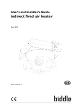
background image

User’s and Installer’s Guide

indirect fired air heater

Model NOZ

Version of Guide: 1.3

GB

a

Summary of Contents for NOZ 25 Series

Page 1: ...User s and Installer s Guide indirect fired air heater Model NOZ Version of Guide 1 3 GB a...

Page 2: ...description of the relevant parts Biddle disclaims all liability for damage resulting from any inaccuracies and or deficiencies in this manual Should you detect any errors or ambiguities in this manua...

Page 3: ...ery check 11 2 2 Preparations for installation 11 2 2 1 Placement of the device 11 2 2 2 Operation 12 2 2 3 Water connections 12 2 2 4 Fitting the roof cowl 13 2 3 Installation of the device 13 2 4 In...

Page 4: ...ice does not heat or heats insufficiently 22 5 Service 23 5 1 Introduction 23 5 2 Safety instructions 23 5 3 Replacing the fan 23 5 4 Replacing the heat exchanger 24 5 5 Replacing a nozzle 25 5 6 Repl...

Page 5: ...he device into operation Familiarise yourself with the operation of the device and follow the instructions carefully 1 2 How to use this guide If you are unfamiliar with the air heater then please rea...

Page 6: ...qualified technical staff when carrying out maintenance or repair 1 2 3 Pictograms on the device and in the guide The pictograms in Table 1 1 refer to possible risks and or dangers You will find thes...

Page 7: ...combination can be supplied with the exception of the combination NOZ 50 with supply voltage E 1 3 4 Type plate You will find the type plate behind the cover of the isolating switch and above the isol...

Page 8: ...RODUCTION AIR HEATER 8 waterside control room thermostat frost protection thermostat set of nozzle caps Ventilation accessories roof cowl interconnecting ducts filter module G2 damper module damper mo...

Page 9: ...he floor It should not be possible to reach the nozzles without the use of mechanical aids Warning w The following instructions are essential for working safely on the device for installation maintena...

Page 10: ...INTRODUCTION AIR HEATER 10...

Page 11: ...ice 1 Make sure that the structure on which the air heater will be suspended is capable of supporting the weight of the device The weight is shown on the type plate see section 1 3 4 2 The device must...

Page 12: ...discharge temperature see section 2 4 1 The dimensions in mm for NOZ 25 NOZ 50 are shown in the drawing on the left 640 865 Supply Return 710 935 512 738 Table 2 1 Specifications of the heat exchanger...

Page 13: ...Installation of the device Note n During the installation period protect the device against damage and against infiltration by dust cement etc The packaging for example can be used for this purpose N...

Page 14: ...water pipework 6 Set the main switch to 0 7 Open the housing of the isolating switch loosen the screw at the bottom of the housing 4 and tilt the cover upwards to remove 5 8 Disconnect the isolating...

Page 15: ...are identical 1 Mount the control valve 1 on the supply pipe of the heat exchanger see also section 2 2 3 2 Fit the thermostatic control element onto the valve 3 Open the housing of the isolating swi...

Page 16: ...ion to the flange using 12 screws 2 2 4 3 Damper section The device can be fitted with a damper section to enable the connection to the ventilation channel to be opened and closed The damper section i...

Page 17: ...cal 1 Check the height at which the device must hang and if necessary fit a channel of the correct length to the roof cowl Caution c The device cannot hang on the roof cowl Use must always be made of...

Page 18: ...n of the fan the fan should when seen from below be rotating anti clockwise 2 7 Preparations for use 2 7 1 Controlling the discharge direction The nozzles are equipped with a ball and socket joint You...

Page 19: ...The user can make the following adjustments 1 Switch the device on off 2 Control the fan position Controlling the discharge direction is not a user action this is set at the time of installation see s...

Page 20: ...OPERATION AIR HEATER 20...

Page 21: ...is is mounted on top of the device This unit contains a drawer in which the filter material lies As standard the filter drawer contains a class G2 filter material It is possible to clean the filter ma...

Page 22: ...tioning of the device 3 Is the device connected to the mains 4 4 2 Device does not heat or heats insufficiently Check the following points If the situation has not improved after you have run through...

Page 23: ...the fan in the housing of the isolating switch See section 5 6 on page 26 4 Loosen the screw 1 in the bottom of the cone and remove the screw 5 Partially loosen the six screws of the cone 2 turn the c...

Page 24: ...eat exchanger 1 Close the isolating valves in the hot water pipework 2 Wait until the device has cooled sufficiently Note n You can accelerate this procedure by allowing the fan to rotate 3 Set the co...

Page 25: ...r parts by following the disassembly steps in reverse order 5 5 Replacing a nozzle 1 Set the control switch to position 0 2 Set the isolating switch to 0 3 Loosen the screw 1 in the bottom of the cone...

Page 26: ...o remove 2 5 Disconnect the isolating switch from the plating use a screwdriver to pull the locking device at the bottom of the isolating switch downwards 3 and then push the switch upwards 4 6 Discon...

Page 27: ...24 I installation control unit 17 device 13 preparations 11 preparations for use 18 L liability 2 M main isolating switch replacement 26 maintenance 21 N nozzle controlling the discharge direction 18...

Page 28: ...5014 2 ont t appliqu s Du fait qu ils respectent ces exigences les produits sont aussi conformes la l gislation nationale E Declaraci n de la CEE sobre contratos de maquinas directiva 98 37 CEE anexo...

Reviews: