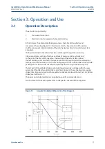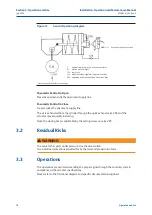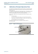
7
0.3
240
93
165
M20
4
5
17
127
70
12
75,6
0.9
310
112
254
M16
8
5
19
150
86
14
93,6
1.5
360
144
298
M20
8
6
19
190
112
18
119,0
3
430
195
356
M30
8
9
23
200
157
25
167,8
6
520
250
406
M36
8
14
29
260
200
28
212,8
Installation, Operation and Maintenance Manual
MAN616_EAC Rev. 5
July 2020
Section 2: Installation
Installation
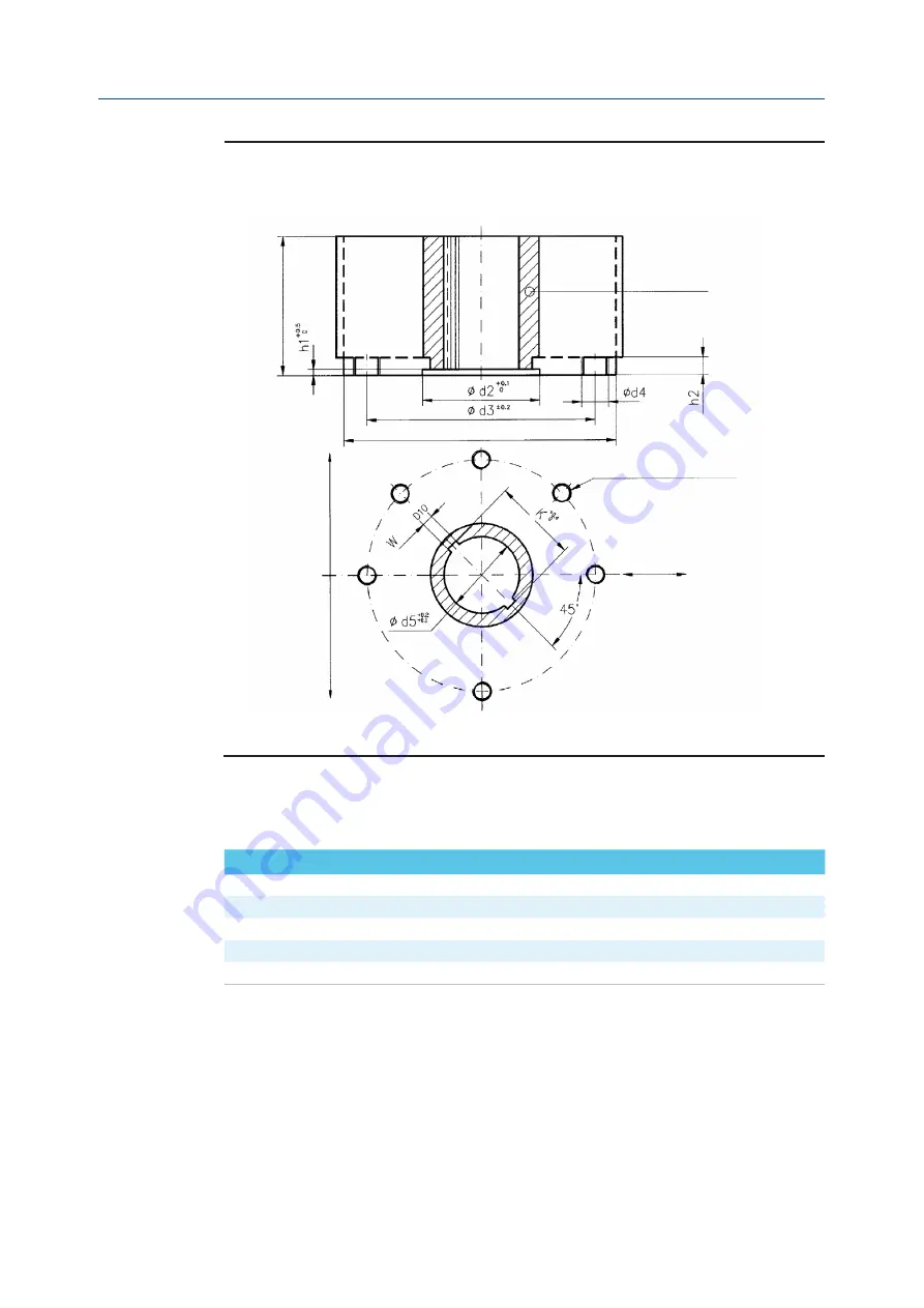
Figure 2
Coupling Dimensions for Scotch Yoke Standard Actuators
Drive sleeve
H m
ax
N
.4 h
ole
s flan
ge
N
.8 h
ole
s flan
ge
N. THREADED HOLES
P.C.D., number and size according to ISO 5211
(but the holes are on centerline instead of
straddle the centerline)
ø d1 max
Flow line
Top view of the scotch yoke mechanism
(actuator shown in closed position)
Models from 0.3 to 6
Dimensions
in millimeters
Actuator model
Ø d
1
Ø d
2
Ø d
3
Ø d
4
N
h
1
h
2
H max
Ø d
5
W
K
Table 2.


