February 2022
Installation, Operation and Maintenance Manual
VCIOM-15345-EN Rev. 1
20
Electrical Connections
Section 3: Electrical Connections
3.4
Separate Terminal Chamber (STC) Connections
3.4.1
Connect the main power supply cables, including an Earth/Ground
(refer to the job specific Wiring Diagram).
3.4.2
Use the barrier strip clamp screws to connect the control wiring
(refer to the job specific Wiring Diagram).
3.4.3
Ensure all connections are hand tight, including any unused terminals.
NOTICE
The main power supply and ground wire connections are screw size M4. The control
connection screw size is M3.
3.5
Replace Terminal Chamber Cover
3.5.1
Clean electrical enclosure threads thoroughly and lightly grease with dielectric
grease before closing.
3.5.2
Replace the cover by reversing the order of the steps to remove the cover.
3.6
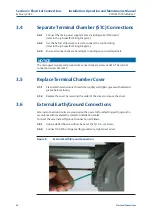
External Earth/Ground Connections
External connection points are provided on the operator for attaching earth/ground in
accordance with local electric codes for installation cables.
Connect the external earth/ground connection as follows.
3.6.1
Using a slotted tip screwdriver, back out the 5/16 in. set screw.
3.6.2
Connect 14 AWG or larger earth/ground wire, tighten set screw.
Figure 8
External Earth/Ground Connection


