September 2019
Installation, Operation and Maintenance Manual
MAN720_IMVS2000v2_IOM Rev. 6
MAN720_IMVS2000v2_IOM Rev. 6
Section 5: Working Principle
Working Principle
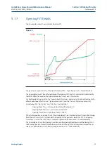
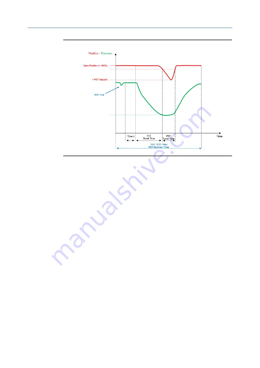
Figure 8
Time A: time from the end of the SOV test and the beginning of the PST test. It is variable time
determined by the IMVS2000v2.
The IMVS2000v2, correctly configured, allows testing two SOVs in series in a unique PST.
During the first PST, the first SOV (SOVA) is briefly used for a short time to generate a pressure drop
inside the cylinder (detected by pressure sensor) without generating the actuator movement.
The second SOV (SOVB) is used to control the valve/actuator to get the setpoint of the PST.
During the next PST the IMVS2000v2 controls the solenoid valve in the opposite sequence: SOVB is
tested by generating a cylinder pressure decrease only and the SOVA is used to get the setpoint of the
PST. After each performed PST, the IMVS2000v2 reverses the solenoid valve test sequence.
It is possible to configure the IMVS2000v2 to test the SOVs individually (“PST Ser. SOVS” = “One”)
During the first PST the SOVA is used to get the setpoint of the PST and the SOVB is not tested.
During the next PST the SOVB is used to get the setpoint of the PST and the SOVA is not tested.
After each performed PST, the IMVS2000v2 reverses the solenoid valve test sequence.
The way to perform the PST of the SOVs in series is determined by the “PST Ser. SOVs” parameter.
See 6 for details dealing with the IMVS2000v2 configuration.
5.1.8.2
SOV B TEST Details
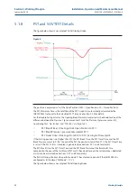
The figure below shows an example of SOV TEST on the SOV B on a system of two SOVs in series
(see for example Configuration C on paragraph 9.2.3). This kind of test is performed in case of the
following settings (see Section 5.1.6):
•
“Act. Mode” = “Single” or “Double-S”
•
“SOVs Qty” = “Simplex”
•
“PST Ser. SOVs” = “Both”
•
“Pr. S. 1-2”
≠ “None”
24
Summary of Contents for IMVS2000v2
Page 2: ......


