EX200 Electro-Hydraulic Actuator Positioner
Bifold Orange Limited.
Drwg. No.: ORM0001 Issue : 1 Date : 24/06/2015 Page :
12 of 20
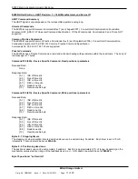
Bit 7
Bit 6
Bit 5
Bit 4
Bit 3
Bit 2
Bit 1
Bit 0
Function
Command
by HART
ESD and
Fault O/P
HART
override
HART
override
HART
override
Solenoid
speed
HART remote
enable
Not assigned
1
Enabled
Separated
Drive Up
Drive
Down
Freeze
Step mode
Enabled
0
Disabled
Linked
Command
Signal
Command
Signal
Command
Signal
Continuous
drive
Disabled
Bit 0:
Not assigned, future use.
Bit 1:
Set
– enables ALL parameter setting via Command 129 (81h) and disables EX200/H front panel adjustments of
stepping timers and dead zone.
Clear
– enables EX200/H front panel adjustments of stepping timers and dead zone and rejects any other
parameter data in Byte 10 (factory default)
Bit 2:
Set
– forces stepping mode, if Bit 1 is set.
Clear
– allows selection of stepping mode via DIL switch position 4 (factory default)
Bit 3:
Set
– stops the actuator and ignores changes in command signal, if Bit 1 is set.
Clear
– positions to command signal (factory default)
Bit 4:
Set
– Drives actuator down, if Bit 1 is set
Clear
– positions to command signal (factory default)
Bit 5:
Set
– Drives actuator up, if Bit 1 is set
Clear
– positions to command signal (factory default)
(Note
– only one of bits of 3,4 and 5 to be set)
Bit 6:
Set
– Separates fault output (triggered from contact break at terminals 15,19) from the ESD output, triggered by a
command or feedback signal break.
Clear
– fault input or signal break triggers both fault output and ESD output (factory default)
Bit 7:
Set
– When bit 2 is set, enables remote command signal via Command 130. Disables analog command input.
Clear
– Disables remote command signal, Command 130.
Command 130 (82h) - Device Specific Command, Write command signal as 0
– 100.0% IEEE 754 floating point
Received Data:
[0-3]
Command signal (SV) as IEEE 754 floating point
Response Data:
[0-3]
Command signal (SV) as IEEE 754 floating point


