background image

5.   Display 


ORM0043_2 

Modulating Controller Application Manual 

Page 9 


5.1   Screen 1 

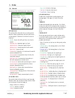
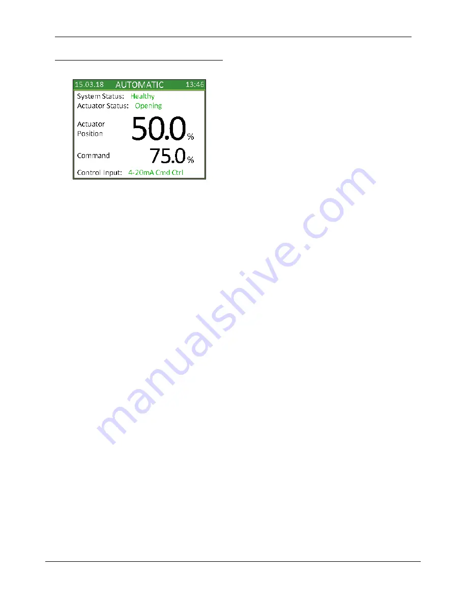
An example of the first display screen is shown below: 


SYSTEM STATUS 

The system status information line is used to provide 
details on the controller status and any faults that are 
currently present. Below are the statuses that can be 
displayed: 

Healthy 

- System is healthy and there are no faults 

present


Feedback Fault 

- Feedback signal is in fault


Command Fault 

- Command signal is in fault


Common Fault 

- External common fault is present


Pump Fault 

- Pump is in fault


Overrun Fault 

- Pump has run continuously beyond its 

maximum allowable time


Low Level Fault 

- Pump reservoir level is below the 

level switch set point


High Temp Fault 

- Pump reservoir temperature is 

above the temperature switch set point


Acc Press Fault 

- Accumulator pressure signal is in fault


Low Press Fault 

- Accumulator pressure is below 

minimum allowable pressure


High Press Fault 

- Accumulator pressure is above 

maximum allowable pressure


Low Supply Press 

- Supply pressure is below minimum 

allowable pressure


Supply Press Flt 

 - Supply pressure signal is in fault 

ACTUATOR STATUS 

The actuator status information line is used to provide 
details on the current movement of the actuator. Below 
are the statuses that can be displayed: 

Stayput - Actuator is stationary 

Opening

 - Actuator is opening 

Closing

 - Actuator is closing 

Open Limit

 - Actuator is fully open 

Close Limit

 - Actuator is fully closed 

Pump Output

 - Pump is running 

ACTUATOR POSITION 

Provides the current actuator position based on the 
analogue signal. If the signal is in fault 0.0% will be 
shown. 

COMMAND 

Provides the demanded actuator position. If in 4-20mA 
command control the 4-20mA signal will be displayed. If 
in remote command control the remote command signal 
will be displayed. If the signal is in fault 0.0% will be 
shown. 

CONTROL INPUT 

The control input status line is used to indicate what is 
currently driving the actuator and aims to show why the 
actuator is in its current state. Below are the list of 
possible control inputs: 

None - There is no control input so the actuator will be 
stationary 

4-20mA Cmd Ctrl

 - Modulating based on the 4-20mA 

command signal 

Remote Cmd Ctrl

 - Modulating based on the remote 

command signal 

Remote Open

 - Opening due to a digital signal 

Remote Close

 - Closing due to a digital signal 

Override Open

 - Opening due to a digital signal and is 

overriding a fault 

Override Close


 Closing due to a digital signal and is 

overriding a fault 

Manual Open

 - Manually opening using the switch 

Manual Close

 - Manually closing using the switch 

Fdbk Fault Open 

- Faulting open due to a feedback 

fault 

Fdbk Fault Close 

- Faulting close due to a feedback fault 

Fdbk Fault Stop

  - Faulting last due to a feedback fault 

Fdbk Fault Stay

 - Faulting last due to a feedback fault, 

but the standard fault position is either open or closed. 

Cmd Fault Open

 - Faulting open due to a command 

signal fault 

Cmd Fault Close

 - Faulting close due to a command 

signal fault 

Cmd Fault Stop

 - Faulting last due to a command signal 

fault 

Summary of Contents for Orange EHPC210

Page 1: ...ower Limited The content of this document may not be used for purposes other than that for which it has been supplied and may not be reproduced either wholly or in part nor may it be used by or its co...

Page 2: ...m Values 13 6 4 System Times 14 6 5 HART Variables 14 This manual provides instruction on the setup and analysis of the modulating controller application Section 2 details specific actuator modules in...

Page 3: ...be linked to the input providing the actuator position signal which provides a calibrated 0 100 value In standard operation 4 20mA Cmd Input should be active meaning that the command value is taken f...

Page 4: ...or both limits of the pulse zone these being the set pulse zone Limit and when the command and actual position are equal Blnce A transfer function is then used within the application to set the requir...

Page 5: ...ide When the controller is in automatic mode if the actuator goes into fault the actuator can be forced to drive to a required location If Fault Open and Fault Close are both off or both are set activ...

Page 6: ...n the actuator will position based on the fault override settings High Pressure SP is a high pressure alarm set point which is used to indicate that the pressure has exceeded the maximum allowable acc...

Page 7: ...uator will position based on the fault override settings To reset Overrun Fault Clear Fault must be set active This immediately resets the fault and then Clear Fault is automatically set to off such t...

Page 8: ...settings because it cannot be certain the pressure has not dropped below the minimum allowable supply pressure 4 2 Controller Access Whenever the controller is powered on the Controller On output is s...

Page 9: ...Actuator is fully closed Pump Output Pump is running ACTUATOR POSITION Provides the current actuator position based on the analogue signal If the signal is in fault 0 0 will be shown COMMAND Provides...

Page 10: ...urrently present Below are the statuses that can be displayed Healthy Accumulator is operating within required limits Pump Output Pump is running Acc Press Fault Pressure signal is in fault Pump Fault...

Page 11: ...signal fault Common Fault Set active when there is a signal indicating an external fault Pump On Demand Set active to enable use of pump on demand features Run Pump To Opn Set active to run the pump w...

Page 12: ...mand signal is in fault Common Fault Set active when there is a signal indicating a common fault Pump Output Set active when the pump is required to run Pump Fault Set active when there is a signal in...

Page 13: ...ic DZ Value indicating how much the command signal must be less than the feedback position when the actuator is static before it starts to close Close Moving DZ Value indicating how much the feedback...

Page 14: ...e position when the actuator is opening Close Limit Move Time that the Close Solenoid pulses active when at the pulse zone limit when the actuator is closing Close Blnce Move Time that the Close Solen...

Reviews: