


5
Isis
®
WWW.BIGASSFANS.COM ©2011 DELTA T CORP. DBA BIG ASS FAN CO. ALL RIGHTS RESERVED
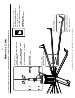
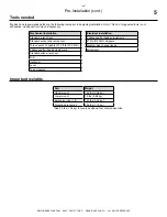
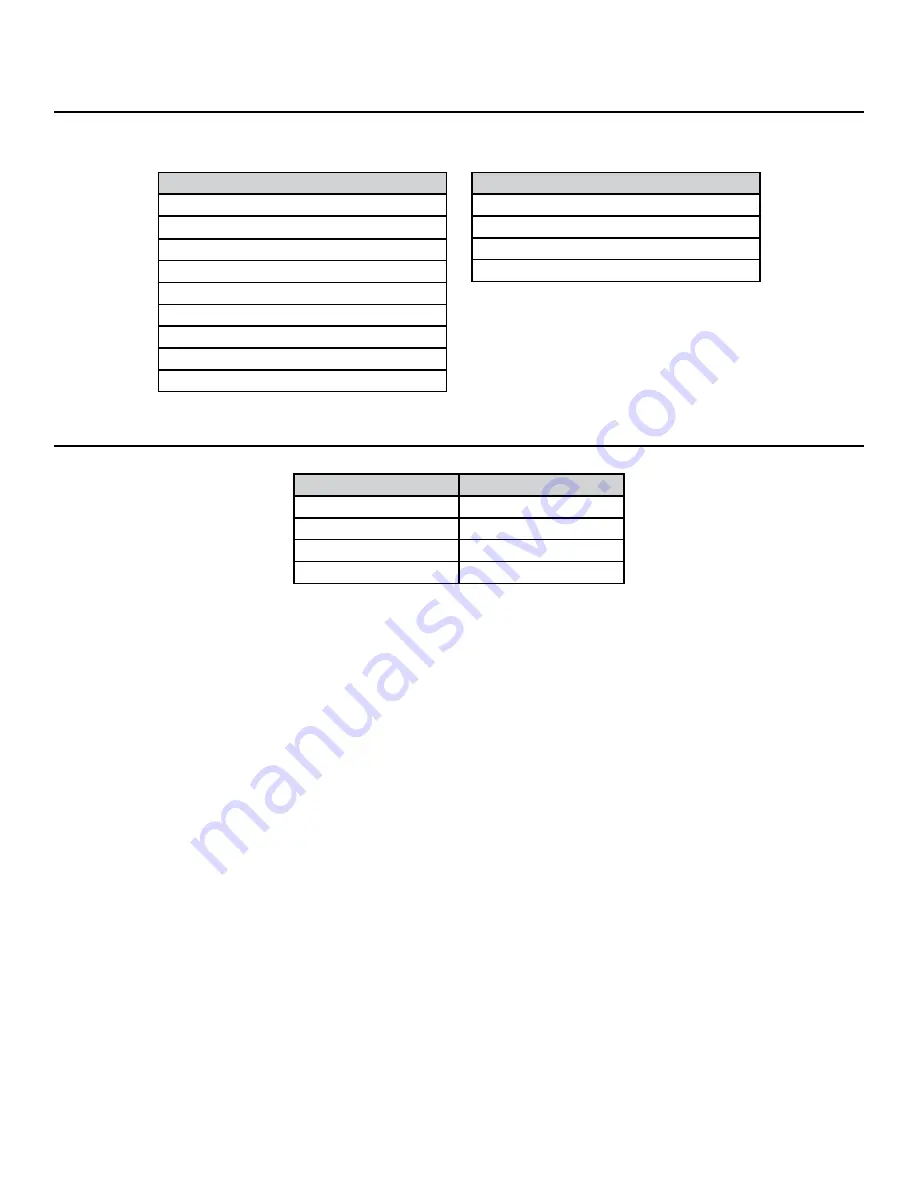
Important weights
Part
Weight
Upper mount
1.24 lbs (0.56 kg)
Lower mount
1.5 lbs (0.68 kg)
Extension tube (1-ft)
1.21 lbs (0.55 kg)*
Mounting bracket kit
2.54 lbs (1.15 kg)
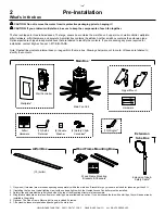
Tools needed
Big Ass Fans recommends gathering the following tools prior to beginning installation.
Note: This list of suggested tools is not
exhaustive. Additional tools may be necessary.
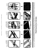
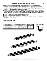
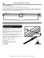
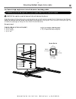
Mechanical installation
Standard wrench set
Standard socket and ratchet set
Torque wrench capable of 25 ft·lb (33.9 N·m)
Phillips and flat head screwdrivers
Standard allen wrench set
Drill
Hacksaw
Level
Tape measure
Electrical installation
Phillips and flat head screwdrivers
#10 to #14AWG strippers
Medium size channel locks
Multimeter
*Add 3.5 lbs (1.58 kg) for every additional foot of extension tube.
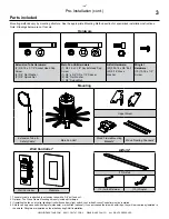
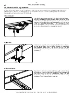
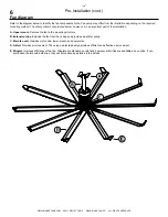
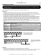
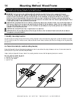
Pre-Installation (cont.)
Summary of Contents for Isis
Page 1: ...INSTALLATION GUIDE For help call 1 877 BIG FANS or visit www BigAssFans com ...
Page 16: ...Notes ...
Page 44: ......
Page 46: ......
Page 52: ......
Page 57: ......
Page 58: ......
Page 59: ......
Page 60: ...REV H 2425 Merchant Street Lexington KY 40511 1 877 BIG FANS 1001250101 1001250101 ...


